Material and Shader Concepts
Shaders are an integral part of the material creation process. This guide provides a conceptual introduction to how shaders work.
Materials and Shaders
A material is an asset that gets layered on top of an object and controls the object’s final appearance on the screen. Materials use shaders to control what the final result looks like.
A shader is a program that runs in the computer’s graphics-processing unit (GPU) to determine how the final surface of the material should look in response to lighting. Shaders are written in a specialized programming language, such as HLSL (High-Level Shading Language) or GLSL (OpenGL Shading Language), that is optimized for the GPU. Shaders often include factors like light absorption, diffusion, reflection, refraction, and post-processing effects in their calculations.
Material Editor is based on GLSL, a high-level shading language with a syntax based on C, used to program shaders in the OpenGL rendering pipeline.
How Does a Shader Operate?
Shader programs control the rendering of graphics in computer and video games, simulations, and other software. This allows shaders to take advantage of the massive parallel processing power of the GPU, which can execute many calculations simultaneously and quickly render complex scenes.
CPU vs GPU
A computer’s central processing unit (CPU) controls and executes the computer’s main operations. The CPU handles a wide variety of tasks, but is not designed to handle many tasks concurrently. The computer’s GPU is a separate processor that is specifically designed for running complex mathematical calculations and rendering graphics, which makes it ideal for executing shader programs. The GPU is designed to handle many tasks and calculations simultaneously.
The Rendering Pipeline
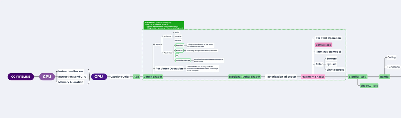
Vertex and Fragment Shaders
There are two types of shaders that run in Material Editor: Vertex shader and fragment shader. A vertex shader always gets processed first, and a fragment shader gets processed afterwards.
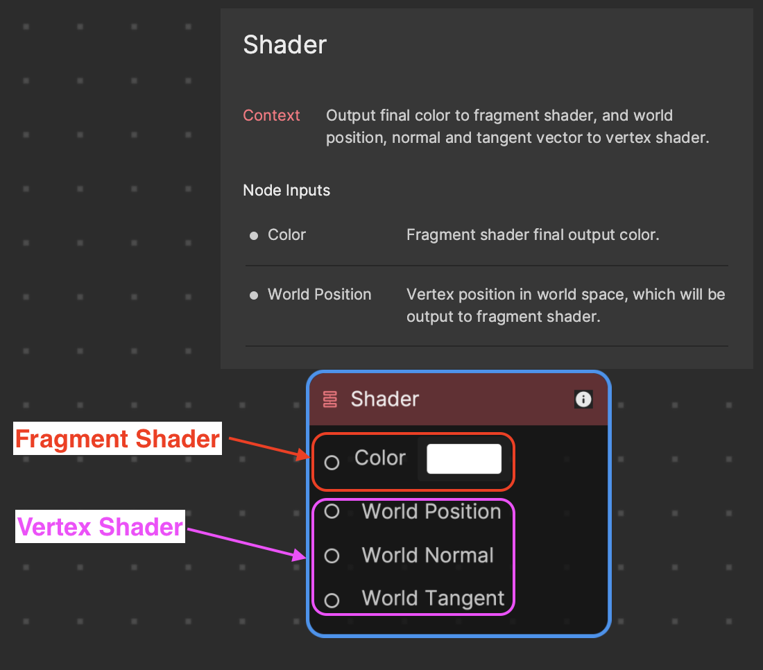
- Vertex shaders transform vertices of the 3D model. These are typically the corners of the polygon on a mesh. This type of shader manipulates the properties of vertices, the points in 3D space that define shapes. Vertex shaders use attributes in their calculations.
- Fragment shaders determine the color of each pixel in the final image. This type of shader determines the color and other attributes of individual pixels.
- Attributes: Geometric attributes refer to the shape, size, and position of an object in a 3D scene. Examples include vertices, edges, and faces in the case of polygonal objects. The following are the three primary attributes used by a vertex shader.
- Position: In 3D computer graphics, position refers to the coordinates (x, y, z) of a point or object in the virtual 3D space. The position can be absolute (relative to a fixed origin) or relative (to another object or point in space).
- Normal: A normal is a vector that is perpendicular to a surface. It’s primarily used in 3D computer graphics for shading calculations. Normal vectors are essential in defining how light interacts with a surface, influencing the appearance of 3D models.
- Tangent: A tangent vector is a vector that’s perpendicular to the normal and lies within the plane of the surface. In the context of 3D graphics, it’s mainly used for texture mapping techniques such as normal mapping and bump mapping. The tangent and the normal together establish a coordinate system (called tangent space) on the surface of a 3D model, allowing textures to be correctly applied.
- Uniforms: These are variables that remain constant for all vertices and fragments during a single draw call, which is a call to the GPU to draw objects on the screen.
- Varyings: These are variables that pass data from a vertex shader to a fragment shader. The goal of a shader is to instruct GPU to paint every pixel on the screen with correct colors.
Material Graphics Concepts
Material creation for 3D modeling requires understanding a few fundamental concepts, including how colors and gradients are applied, how 2D textures map onto 3D models, and more.
Color
In digital graphics, the color of a pixel is determined using the RGBA system, which stands for Red, Green, Blue, and Alpha. These four color components are represented in shader programming with values ranging from 0 to 1. The combination of these components results in the final color displayed on the screen. The Alpha component represents the opacity level, with 0 indicating full transparency and 1 indicating full opacity. RGBA can also be symbolized as XYZW.
Here are a few examples using the vec4 color representation in shader programming:
- White: vec4(1.0, 1.0, 1.0, 1.0); represents maximum intensity of all color components.
- Black: vec4(0.0, 0.0, 0.0, 1.0); implies absence of all color components.
- Red: vec4(1.0, 0.0, 0.0, 1.0); indicates maximum intensity of the Red component.
- Green: vec4(0.0, 1.0, 0.0, 1.0); shows maximum intensity of the Green component.
- Blue: vec4(0.0, 0.0, 1.0, 1.0); represents maximum intensity of the Blue component.
Each vec4 command sets the corresponding RGB values, influencing the final color output.
You can get a variety of colors by mixing RGB values:
- Yellow: vec4(1.0, 1.0, 0.0, 0.0)
- Cyan: vec4(0.0, 1.0, 1.0, 1.0)
- Magenta: vec4(1.0, 0.0, 1.0, 0.0)
Take the example below to see how coloring works using the vec4 system in Material Editor.
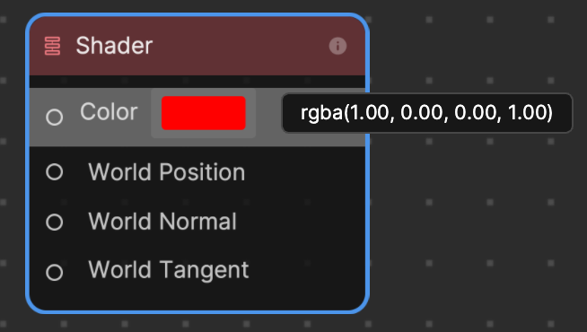
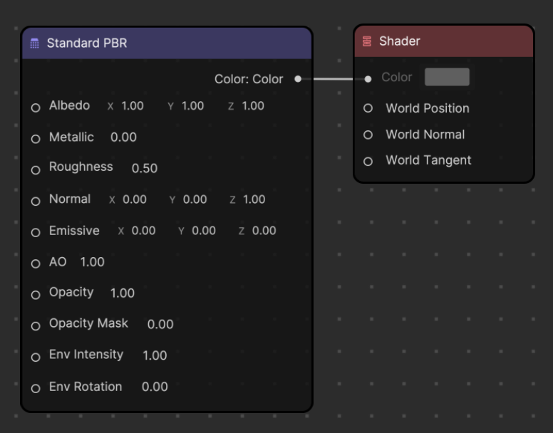
A vec4 of rbga(1.00, 0.00, 0.00, 1.00) results in a red color. This can also be symbolized as XYZW(1.00, 0.00, 0.00, and 1.00). A Constant Float value of 1.00 is assigned to the X and W inputs of the Append4 node, while a Constant Float value of 0.00 is assigned to Y and Z.
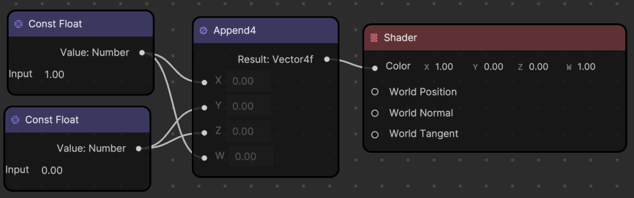
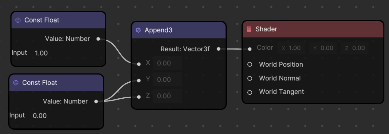
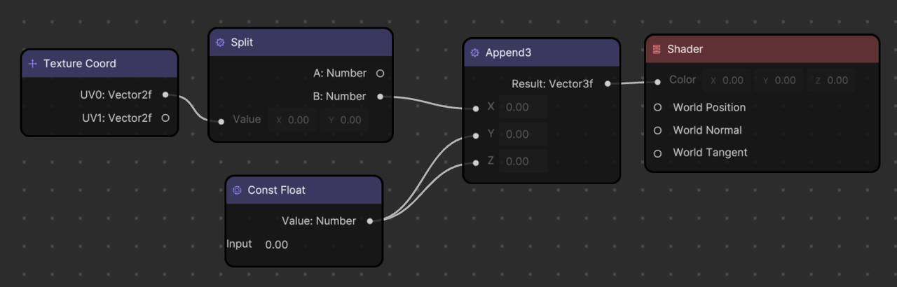
You can also use the Append3 node instead of the Append4 node. Material Editor automatically assumes that the last vector Alpha value is 1.00.
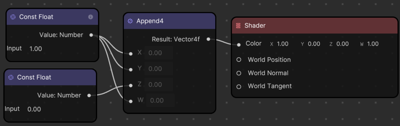
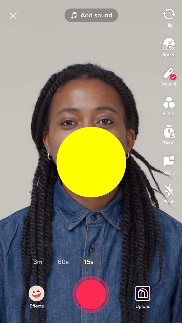
You can also mix color. For example, mixing red and green corresponds to XYZW(1.00, 1.00, 0.00, 0.00), which results in a yellow color.
Texture
In computer graphics, a texture is an image or a portion of an image that is applied, like wallpaper, onto the surface of a 3D model, adding realistic colors and details. When applied to a material, textures can greatly enhance the visual realism of the rendered object.
A material is a set of properties that define the appearance of an object. It can include the base color, reflectivity, transparency, and more. When a texture is applied to a material, it defines the material’s appearance at each point across the surface of the 3D model.
Textures can be used in a number of ways in a material:
- Diffuse or color textures: These give the main color to a material. They often represent the basic pattern or color of the material, like the skin on a character or the bricks on a wall.
- Bump or normal textures: These are used to give the illusion of depth on a surface by altering the way light interacts with it. Bump maps create the illusion of depth and texture on the surface of a 3D model by varying the amount of light reflected at different points on the surface, without actually changing the model’s geometry. Normal maps are a more advanced type of bump map that use RGB information to create a greater sense of depth and detail.
- Specular or reflection textures: These control the shininess and highlight color of a material. They indicate how much of the light hitting the surface gets reflected in a single direction, like a mirror, versus being scattered in multiple directions.
- Opacity textures: These are used to make parts of an object transparent or translucent.
- Displacement textures: These textures actually modify the geometry of a model, displacing the vertices of the mesh based on the brightness of the texture at each point.
- Emissive textures: These textures make the material appear as though it is emitting light. The use of textures in materials can greatly enhance the realism of a 3D scene by creating complex surfaces without requiring detailed geometry.
UV Coordinates
In graphics programming, UV coordinates are a way of mapping a 2D texture onto a 3D object. The UV coordinates represent the 2D position of a pixel in a specific texture, and are typically stored as a vector with two components: UV.x and UV.y.
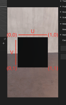
In a shader, UV.x and UV.y are used to sample the texture at a specific position. For example, if you want to color a pixel on a 3D object with a texture, you would use the UV coordinates of that pixel to sample the texture at that location.
The UV.x component represents the horizontal position of the pixel in the texture, ranging from 0 to 1. A UV.x value of 0 corresponds to the left edge of the texture, while a value of 1 corresponds to the right edge.
The UV.y component represents the vertical position of the pixel in the texture, also ranging from 0 to 1. A UV.y value of 0 corresponds to the top edge of the texture, while a value of 1 corresponds to the bottom edge.
Together, UV.x and UV.y form a vector that specifies the position of the pixel in the texture. By sampling the texture at this position, you can retrieve the color and other attributes of the texture that correspond to the pixel on the 3D object.
Gradient
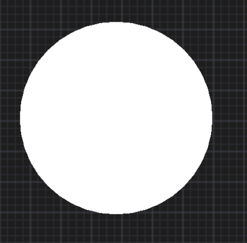
You can also get a gradient of color based on UV coordinates.
Because a UV.x value changes from 0 (left) to 1 (right), if you feed this UV.x value to the R value in RGB, you get a gradient of black (0, 0, 0) to red (1, 0, 0).
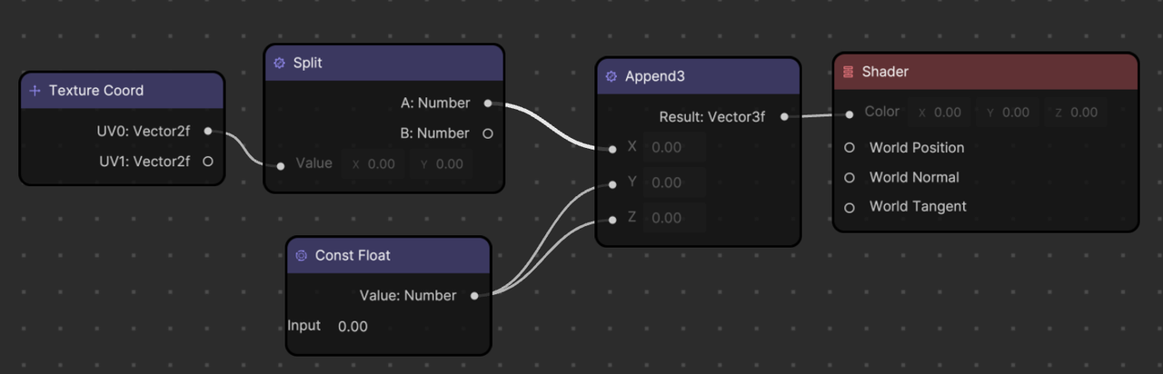
You can also use the UV.y value to change the gradient direction. Since the UV.y value changes from 0 (top) to 1 (bottom), feeding this UV.y value to the R value in RGB gives you a gradient of black (0, 0, 0) to red (1, 0 0).
Shading Models
Shading models, also known as lighting models or illumination models, are mathematical models used to calculate the appearance of surfaces in 3D space when light interacts with them. They take into account the position and properties of light sources, the position and orientation of the surface (given by the position, normal, and tangent), and the material properties of the surface to calculate the final color of each pixel.
In the real world, the way one perceives an object’s color and texture is largely determined by how light interacts with the object’s surface, including how light is absorbed, reflected, and transmitted. Different materials have different responses to light, which is why a shiny metal ball looks different from a fuzzy tennis ball under the same lighting conditions.
Similarly, in computer graphics, the shading model mathematically replicates these light and surface interactions to generate a realistic mage. Shading models help to establish an object’s appearance in terms of color, brightness, and depth, which brings a sense of three-dimensionality to the object.
Different shading models, such as Flat shading, Gouraud shading, Phong shading, or physically based rendering (PBR), offer different levels of realism and computational complexity.
For example, Flat shading, which gives a single color to each face of an object, is simple and fast, but it doesn’t look very realistic. On the other hand, Phong shading, which considers the angle of the light and the viewer’s position to compute the color of each pixel, is more complex but produces more realistic and smoother images.
Without a shading model, 3D graphics would appear flat and unrealistic. Therefore shading, though computationally intensive, is a vital aspect of rendering in computer graphics.
The following shading models are available for use as nodes in Material Editor.
- Standard Unlit: Unlit materials are not affected by light
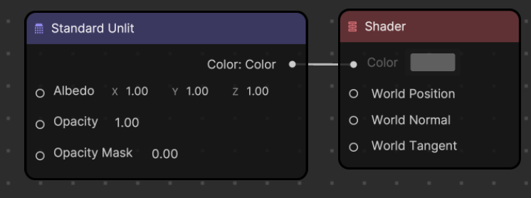
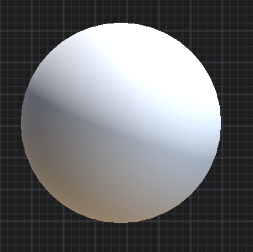
- Standard PBR: PBR materials are affected by light under the rules of real world lighting
Screen Coordinates
Screen coordinates are a set of two-dimensional coordinates that correspond to the pixels or points on the screen. The X-axis represents the horizontal position of the element on the screen, while the Y-axis represents the vertical position of the element on the screen.
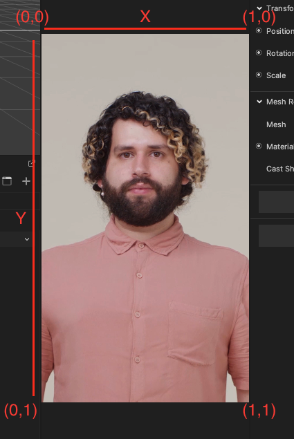
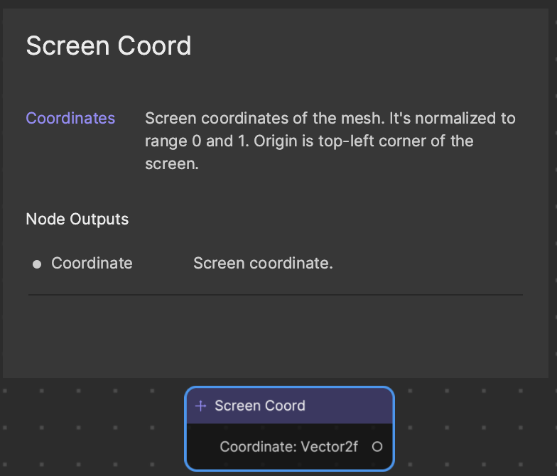
The Screen Coord node contains a Vector2f data type, which refers to X and Y values. The X value goes horizontally (left = 0 and right = 1) and the Y value goes vertically (bottom = 0, top = 1).
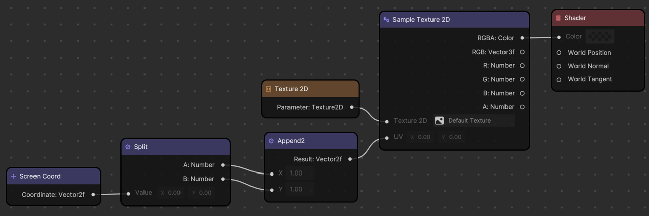
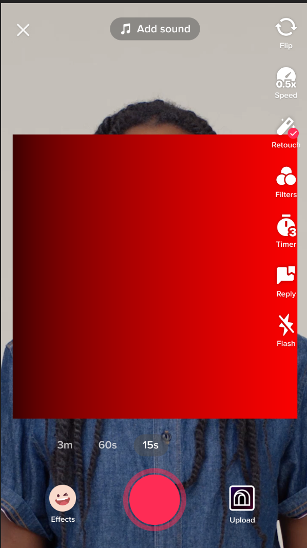
Example: Mirror Screen Effect
A mirror screen effect can be created in Material Editor using the following flow of logic.

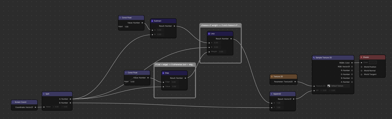
This node-based material graph corresponds to the following program in GLSL.
precision mediump float;
uniform sampler2D u_texture_0;
uniform vec2 u_resolution;

void main() {
    vec2 uv = gl_FragCoord.xy/u_resolution.xy;

    //if uv.x is bigger than 0.5 (right-half of the screen), reverse uv.x's output
    if (uv.x > 0.5) {
      uv.x = 1.0 - uv.x;
    }

    gl_FragColor = texture2D(u_texture_0, uv);
}