Dissolve
The Dissolve material uses random noise to erode the opacity of a surface as if it were dissolving into thin air. An optional color can be added to the border between the surface and the dissolved area.
Download the following file to import the Dissolve material to your Effect House project:
Configure the Graph for Dissolve
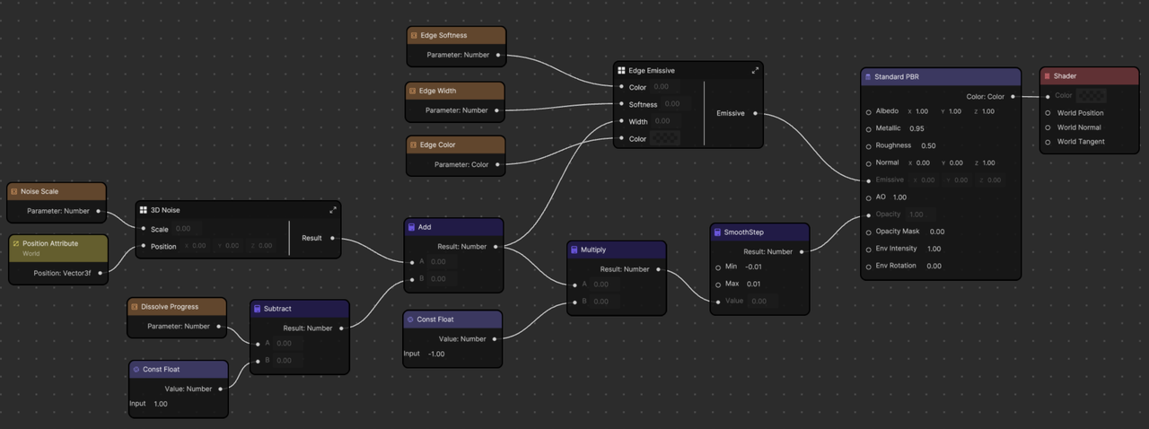
The Dissolve material graph sets data for two input ports in the Standard PBR node: Emissive for the edge color and Opacity to make the dissolved parts transparent.
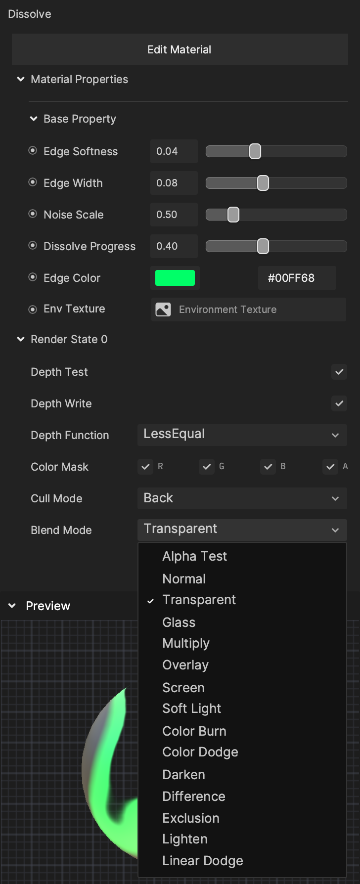
When creating a transparent material that sets the opacity of the Standard PBR node, or the alpha channel of the output color, make sure to change the material’s Blend Mode property to Transparent.
Emissive Properties
| Parameter | Description |
|---|---|
| Edge Color | This parameter is a Color type variable which is added to the areas bordering the dissolved parts of the surface based on the other parameters. Since Edge Color is connected to the Emissive input of the Standard PBR node instead of Albedo, it isn’t affected by scene lighting. Edge Color is also blended additively, meaning if the Edge Color is set to black, no color will be added. See the demonstration below. |
| Edge Softness | Controls how smooth the gradient is between the added edge color and the regular surface. See the demonstration below. |
| Edge Width | Controls the size of the emissive edge. See the demonstration below. |
Demonstrations
Edge Color
Edge Softness
Edge Width
Opacity Properties
| Parameter | Description |
|---|---|
| Noise Scale | Controls the scale of the random noise used to drive the dissolve opacity. See the demonstration below. |
| Dissolve Progress | This parameter controls the amount of the surface that has been dissolved. Try setting it from within the Visual Scripting graph to create a smooth animation. See the demonstration below. |
Demonstrations
Noise Scale
Dissolve Progress
Deep Dive on the Graph of Dissolve
Sampling Noise in 3D Space
For this effect, you must incorporate random noise to add interesting visual details to the Dissolve pattern. The best way to accomplish this would be to sample a noise node with the model’s texture coordinates. However, there are several tradeoffs to consider. Not every mesh has texture coordinates, and although software exists to automatically generate them, they aren’t always high quality and can introduce visible seams, distortions, and areas of noticeably higher or lower resolution.
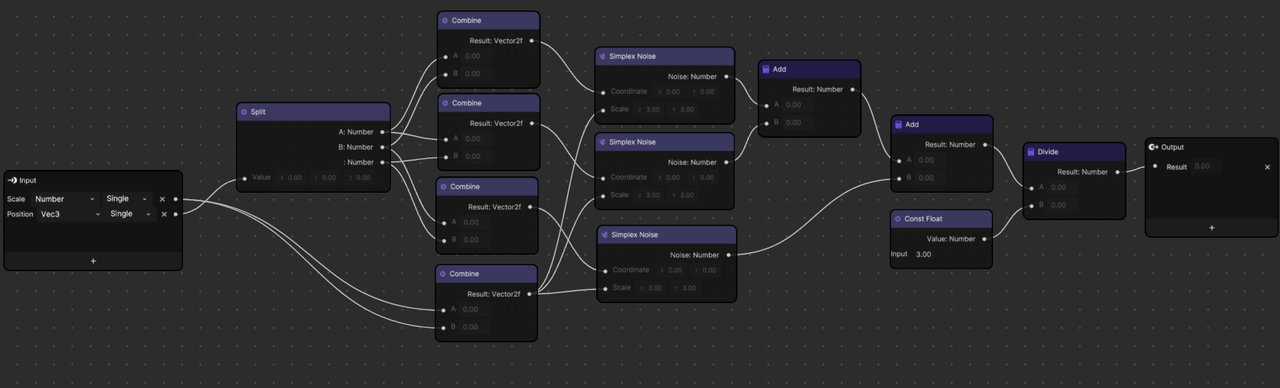
Instead of using texture coordinates, the noise using the position in 3D space is used. However, the existing noise nodes only support 2D coordinates, so this subgraph is included as an example of how to work around that limitation. The 2D noise is sampled 3 times, using position.xy, position.xz, and position.yz, then divided by 3.0 to average the samples and return the final result.
SmoothStep Operator
The SmoothStep node is used twice, both in the main outer graph and inside the edge color subgraph, to provide a configurable way to remap a value into the [0, 1] range that we can then use as a mask for many purposes. For example, setting the opacity or compositing multiple layers together.
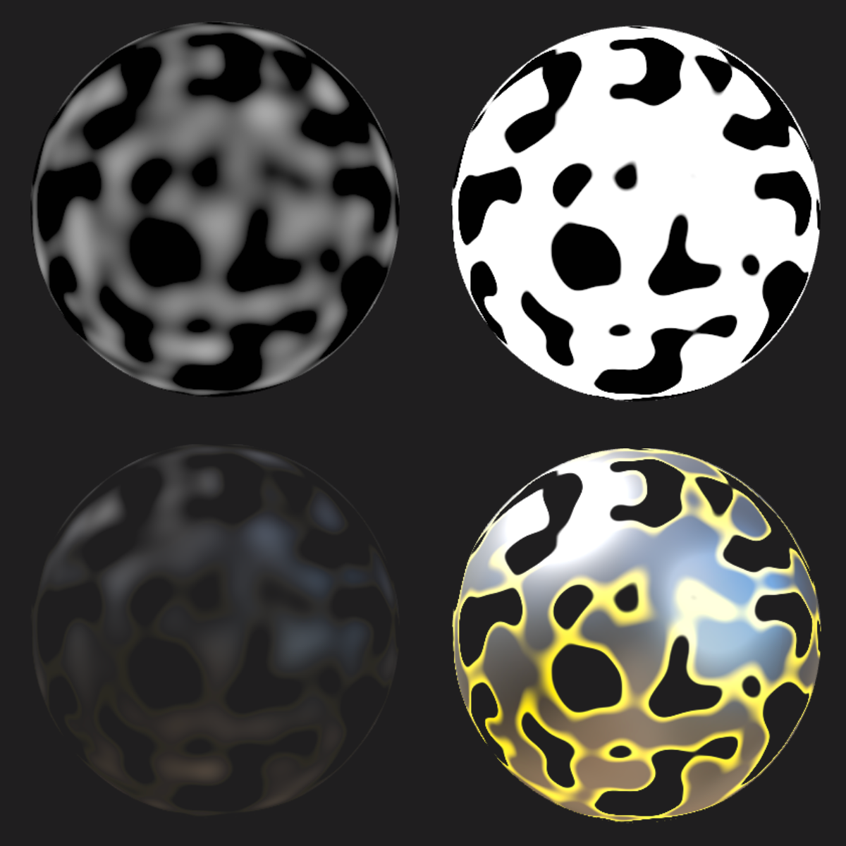
In this image, the top two spheres show the opacity mask fed into the Standard PBR node, and the bottom two show the result. On the left, the SmoothStep node is skipped and the raw noise output is used. On the right, the noise has been remapped into the [0, 1] range.
The SmoothStep node has two additional inputs apart from the value being remapped: a minimum and a maximum. Values below the minimum will return 0, and values above the maximum will return 1. If a value lies between the minimum and maximum, it will be remapped using Hermite interpolation, which produces a smooth gradient between 0 and 1. The larger the difference between the minimum and maximum, the smoother the gradient will appear.
Animating the value of the SmoothStep node’s min and max inputs from 0.0 to +-0.20
SmoothStep is not the only way to remap a value into the [0, 1] range, but it has useful properties that set it apart. For example, the Step node will also return a 0 or 1 depending on if the value passed into it is greater or less than a given edge value. However, since it only accepts 1 edge value instead of the 2 edge values of SmoothStep, and therefore doesn’t return a smooth gradient, neighboring pixels will change directly from 0 to 1 and produce visible jagged edges, known as aliasing.
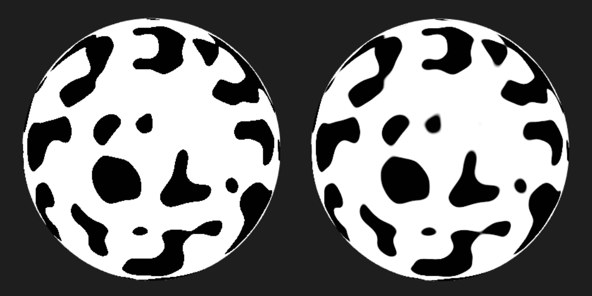
The mask on the left was generated using a Step node, while the one on the right uses SmoothStep.
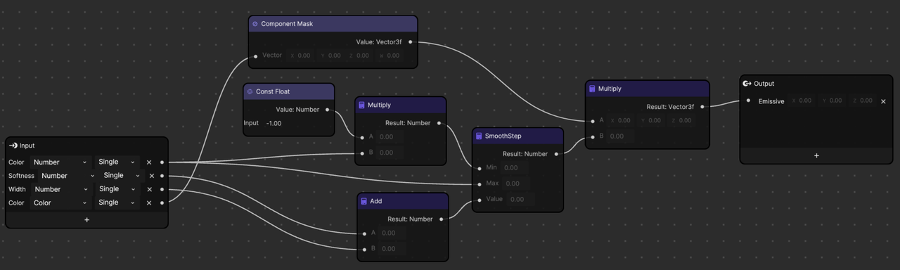
As you can see, the Edge Emissive subgraph is mostly a wrapper around a SmoothStep node: