Material Editor Node Overview
Introduction to Nodes
In Material Editor, a node represents a specific operation or function. Each node can perform a variety of tasks such as blending colors, performing mathematical operations, or controlling the flow of logic. This guide describes the different types of nodes, how to add and use them, and how to configure their parameters.
Add a Node
You can add nodes from the Node menu. There are three ways to access the Node menu in Material Editor:
- Click the Add node button in the toolbar.
- Right-click anywhere in the dotted space, then select Add node.
- Double-click anywhere in the dotted space.
Hovering over an individual node in the menu shows a description of the node’s information, inputs, and outputs.
Configure Node Settings
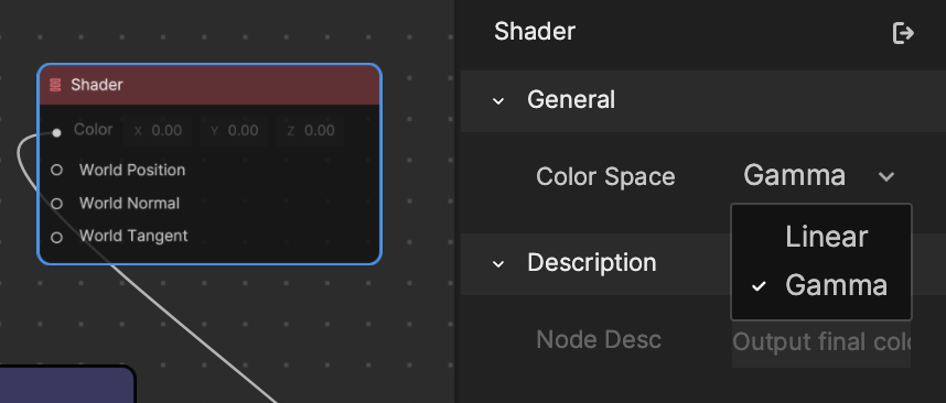
Some nodes have adjustable settings that you can access through the Details button. To view these settings, select your desired node, and then click on the Details button to open the Details sidebar. If your node has an adjustable setting, it will show up in the sidebar. For example, if you click on the Shader node, you can set the Color Space to either Gamma or Linear.
Node Descriptions and Functions
Each node performs a specific function. Click the node’s information button to check out its functionality. Use these descriptions to better understand how the node works and how it can be used within a flow of logic.
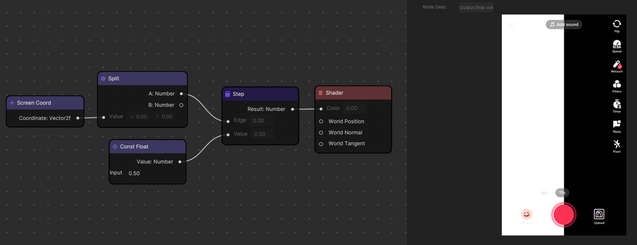
- if (value < edge), return 0
- else (value > edge), return 1
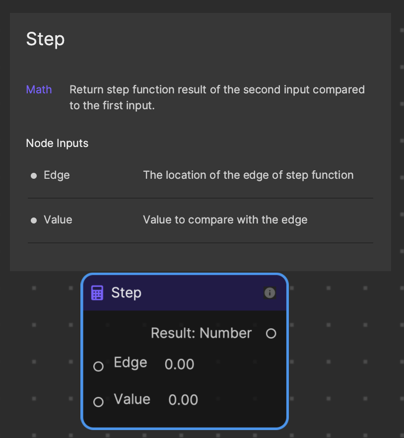
In the following logic flow, the Screen Coord node is made up of 2 vectors: UV.x and UV.y. The Split node splits the screen coordinates into its constituent values, so they can be manipulated independently. The Step node takes one of the split coordinates and compares it against a Value from the Const Float node.
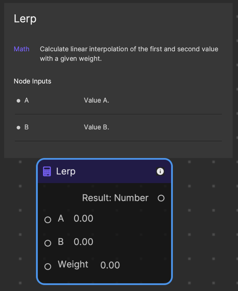
Lerp is another commonly-used node that stands for “Linear Interpolation.” This means it calculates the value at a specific point between two known values.
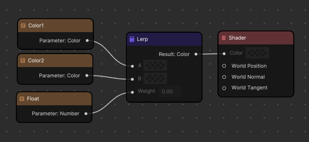
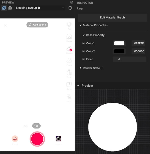
In this example, the Lerp node outputs a mixture of Color1 and Color2 based on the value of its Weight input.
Node Categories
Material Editor has a variety of nodes grouped under different categories:
- Blends: Mixes colors or performs other color operations
- Color: Generates color values
- Constant: Provides constant values
- Coordinates: Generates or manipulates coordinate values
- Gradient: Generates gradient values
- Logic: Used for logic operations
- Material Mode: Determines the shading model of a material
- Math: Used for various mathematical operations
- Noise: Generates noise patterns
- Sample: Used for sampling textures or gradients
- Utility: Various utilities to handle some calculations in an easy way
- Vector Operations: Performs operations on vector values
- Vector: Vector that represents the position, normal, tangent and color attributes of a mesh
Additionally, Parameter nodes, which provide variable parameters, can be accessed from the My Items sidebar. To add a Parameter node, click the My Items button in the Material Editor toolbar, then click the Add button [+] next to Parameters. Select your desired parameter, and then click the button next to the parameter name to add it as a node.
The Material Mode node category has the Standard PBR and Standard Unlit nodes, which influence the material’s properties and determine the material’s color under lighting. You can use these nodes to create solid-color materials, translucent materials, and create texture maps.
Node Use Cases
Material Editor nodes can be leveraged in a variety of ways to achieve different outcomes. For example, specific nodes can be used to map textures to 3D objects, generate color values, and animate the surface texture of a model. The following sections provide an overview of how certain nodes can be used.
Texture Mapping
When making materials, it is often necessary to use various texture resources. Color maps, normal maps, metallicity maps, and ambient occlusion (AO) maps are commonly used. Sampling refers to the process by which the graphics processing unit (GPU) interprets textures. Texture mapping requires specific sampling nodes to project a 2D texture onto a 3D surface. For example, think of a flat map of the world that gets transposed onto a globe.
Material Editor currently supports sampling of 2D textures and cube textures.
Sample Texture 2D
The Sample Texture 2D node can be used to sample 2D maps such as color, normal, metallicity, AO, and more.
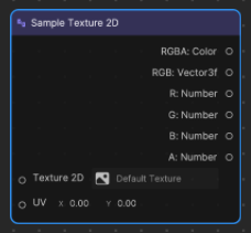
Texture 2D: The 2D texture
UV: UV coordinates. The UV0 of the model is used by default.
Different settings need to be configured when sampling different maps.
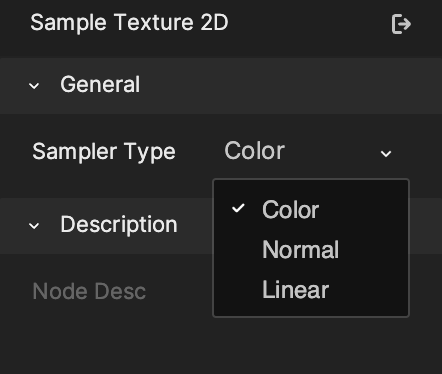
Sampler Type:
- Color: Sample color map
- Normal: Sample normal map
- Linear: Sample other textures
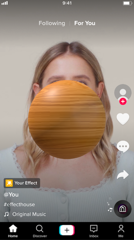
Color Map
The Texture 2D parameter node connects to the Sample Texture 2D node’s Texture 2D input. The Sample Texture 2D node’s Sampler Type is set to Color. The Color setting will convert the texture from gamma space to linear space. Textures drawn on the computer are in gamma space and cannot be used for linear calculations. They need to be converted to linear space first.
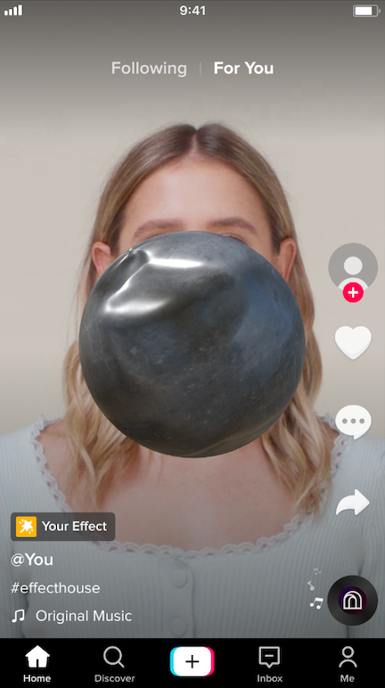
Normal Map
Normal mapping implement’s a surface’s bumps, ridges, and dents. Set the Sample Texture 2D node’s Sampler Type to Normal in the Details sidebar. The sampled normals are generally in the normal space and can be connected to the Standard PBR node’s Normal input. For example, normal mapping can simulate metal surface depressions.
Metallicity/AO map
The textures obtained by baking, such as metallicity and AO mapping, do not need gamma correction. The Sampler Type is set to Linear.
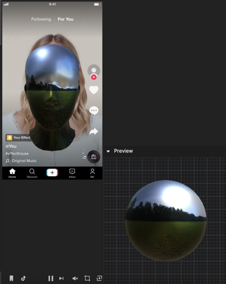
Sample Texture Cube
Cube mapping samples the textures of each of a cube’s six faces, inputs the 3D direction, and then samples the color of the direction on the cube. Sampling uses the Sample Texture Cube node.
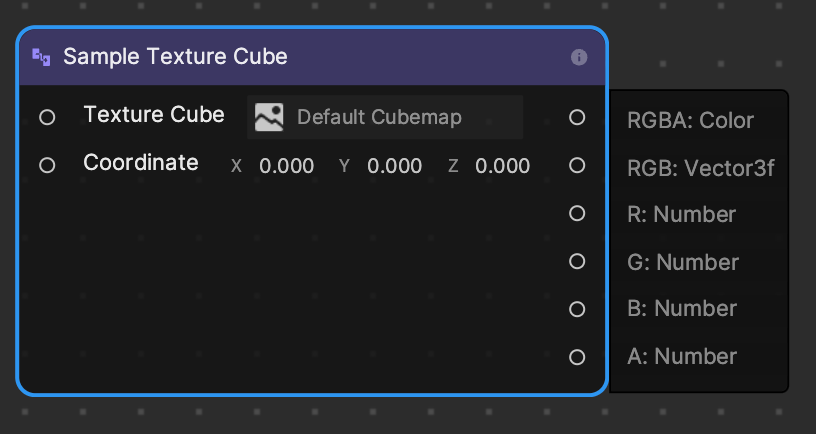
Texture Cube: Cubemap texture
Coordinate: 3D direction of the sampling cubemap
Usage example:
The Texture Cube input connects to the Texture Cube parameter’s node, and the Coordinate input connects to the sampling direction. You can use the local coordinates of the model vertices. Select the cubemap texture in the parameters panel.
Noise
Noise classification nodes such as Gradient Noise, Simplex Noise, and Voronoi Noise are used to generate noise maps which can be used to create irregular effects, such as the effect of irregular deformation of vertices.
Gradient Noise
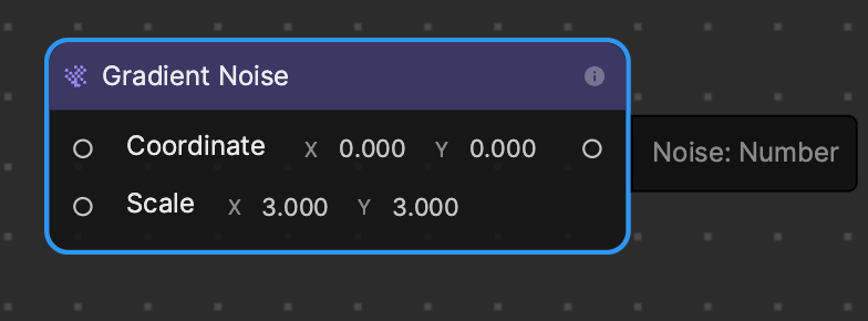
Coordinates: UV coordinates
Scale: The degree of scaling. The larger the scale, the larger the range of Noise seen, and the denser the Noise.
Simplex Noise
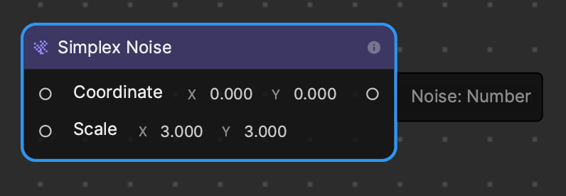
Coordinates: UV coordinates
Scale: The degree of scaling. The larger the scale, the larger the range of Noise seen, and the denser the Noise.
Voronoi Noise
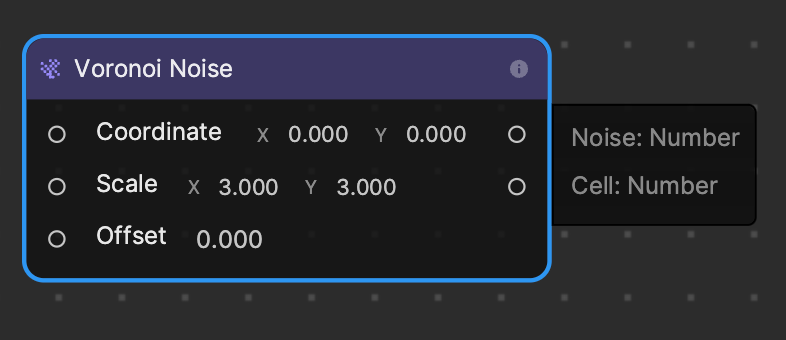
Coordinates: UV coordinates
Scale: The degree of scaling. The larger the scale, the larger the range of Noise seen, and the denser the Noise.
Offset: Offset of Voronoi Cell Center
Color and Gradient
Color and Gradient category nodes like Color Lerp, Angle Gradient, Linear Gradient, and Diamond Gradient are used to generate color or gradient values.
Color Lerp
Angle Gradient
Linear Gradient
Diamond Gradient
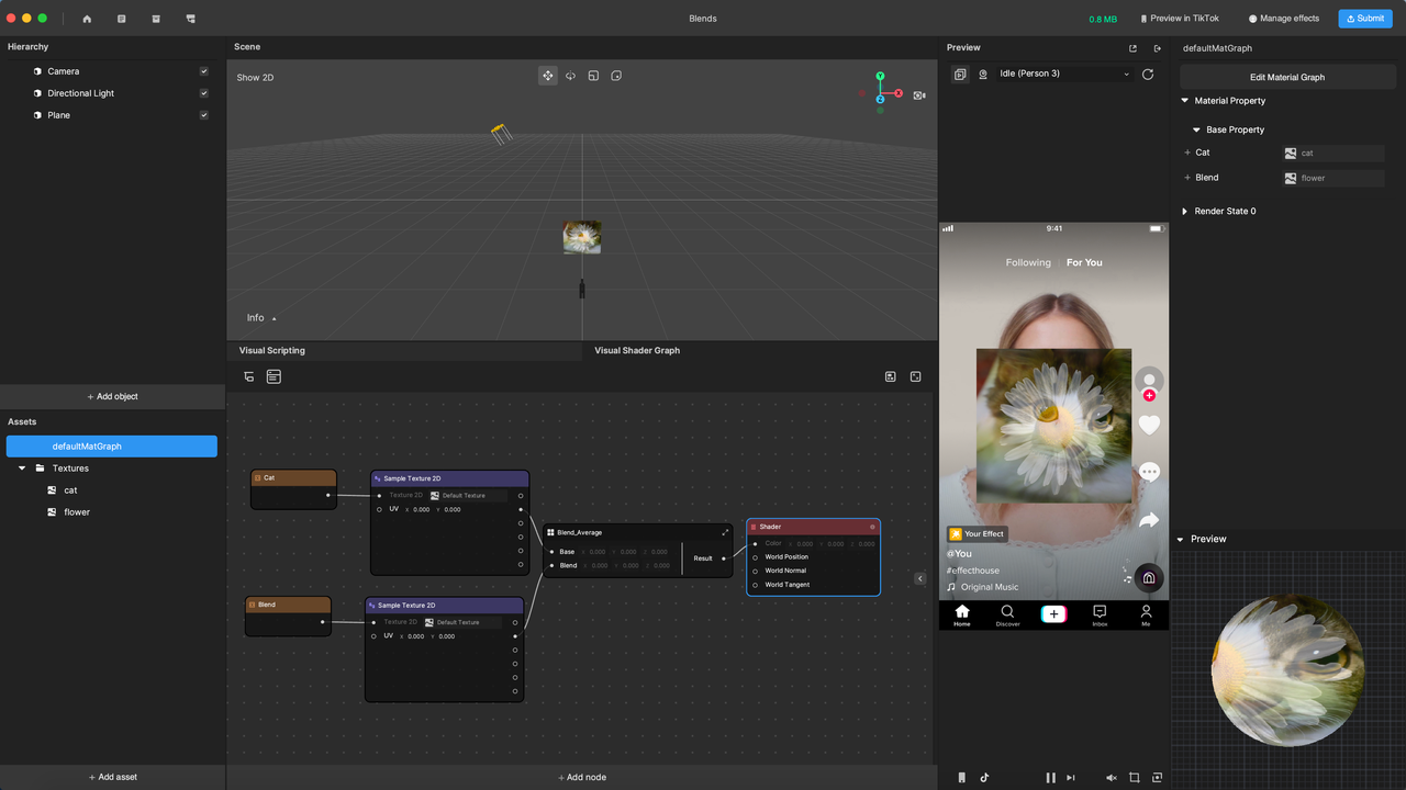
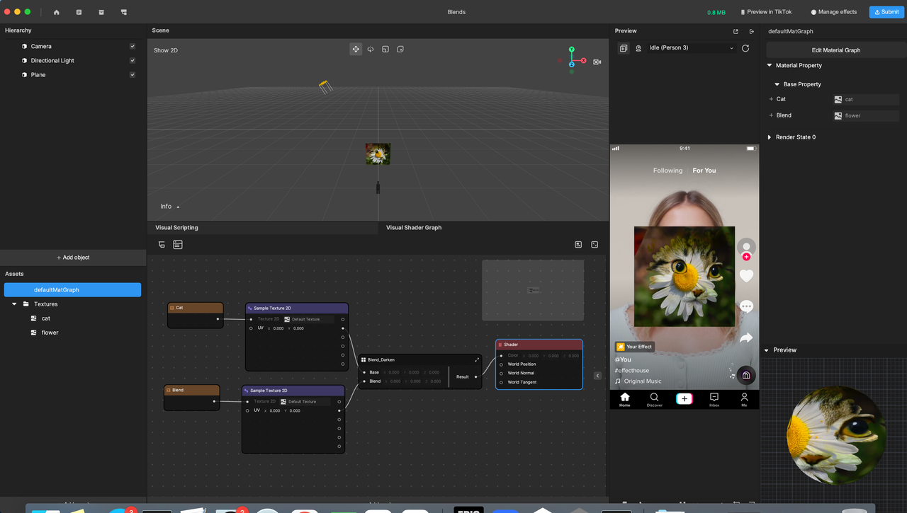
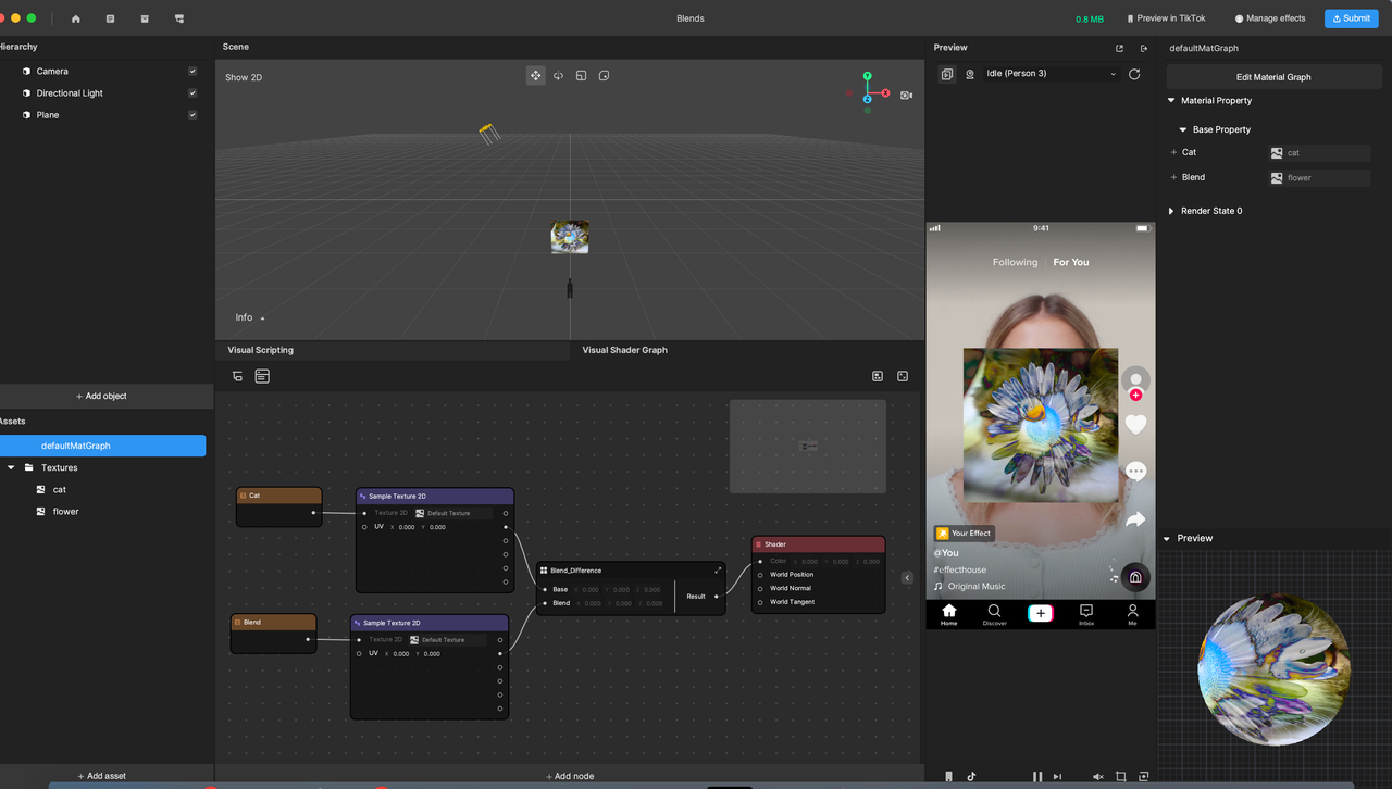
Blends
The Blends category contains nodes that are used for color mixing calculations, which output mixed color. There are 16 blend modes supported.
Average
Darken
Difference
UV Animation
UV Animation is achieved by continuously changing UV coordinates to animate the surface texture of the model.
Built-In Attributes & Uniforms
Material Editor also provides nodes that can access the model’s vertex attributes and the built-in uniforms of the engine. These include nodes for accessing position, normal, tangent, and color attributes. By using these nodes, you can create materials that respond dynamically to changes in the model or the scene.
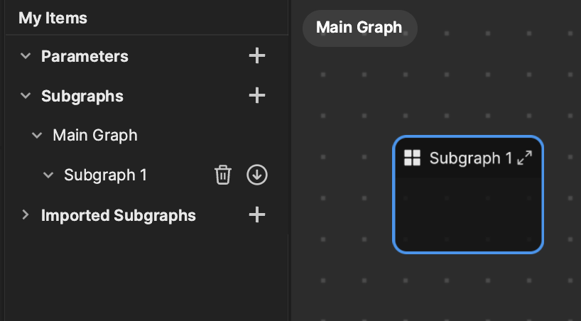
Subgraphs
Subgraphs allow you to encapsulate multiple nodes into a single grouping. This is helpful when you want to use the same group of nodes multiple times in a project.
To create a subgraph, select your desired nodes, right-click on the screen, and then select Create subgraph. You can access your subgraphs from the My Items sidebar.