Side Scroller Game
This MicroJam project was created using Effect House 2.3.0 and with the older canvases. The logic used in this project can be applied to your own game in all version of Effect House. However, to best replicate this project, it is recommended that you use Effect House 2.3.0 or an earlier version.
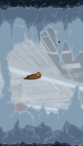
This MicroJam project gives an example of an “endless side scroller” style mobile game. The purpose of this project is to help intermediate Effect House creators increase their experience and knowledge, and show game developers that are new to Effect House how to do some core game practices within Visual Scripting.
We’ll start by doing a high-level walkthrough of the project to see the overall setup. Next we’ll walk step-by-step through the following three main sections:
- Level movement
- Character controls and physics
- Collision detection
We’ve also made an effort to abstract as many pieces of this project as possible for general use cases, so that any creator can export the subgraphs out or reuse the logic for similar game-mechanic designs of their own, without much modification. Just in case you need a refresher, subgraphs are a set of nodes that are grouped together to help better organize the Visual Scripting panel. This project should inspire you to create your own games. Stick around until the end for ideas on how to modify this project to make it more interesting and complete.
Featured Subgraphs
Due to the focus of this MicroJam project on education and learning techniques, the complexity is higher and the building blocks are less isolated. Here are the three different subgraphs that will be featured in this project:
- SimpleRigidBody
- MoveSeamless
- MoveObject
One subgraph from this project that can be reused in various situations, with no issues, is the SimpleRigidbody subgraph.
SimpleRigidbody allows you to add a continuous force to a 2D object by inputting its current position and then outputting its new calculated position in every frame. It will accelerate realistically based on this force applied. Learn more about the details in the Bat Controls section.
The MoveSeamless subgraph is one example of how you can drive a looping background to continuously pass. This subgraph is more hard coded to the project, but can be used in a lot of scenarios. It’s best to read the Level Movement section for a full explanation on how it works in this project.
Lastly, the MoveObject subgraph can be a useful subgraph if you’re creating a 2D scene where you want an object to routinely enter from one side and pass by a character. Again, you can find a full explanation in the Level Movement section below.
Feel free to follow along this video tutorial!
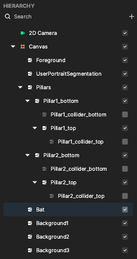
Hierarchy
The entire project uses a single camera, with only one canvas, and everything is in one layer.
High-Level Visual Scripting Overview
The top-level Visual Scripting has the following three main parts:
- The main game mechanics in the top left.
- The game initialization at the bottom.
- Some extra bits at the top right that show or hide the user segmentation depending on whether there is a face detected or not.
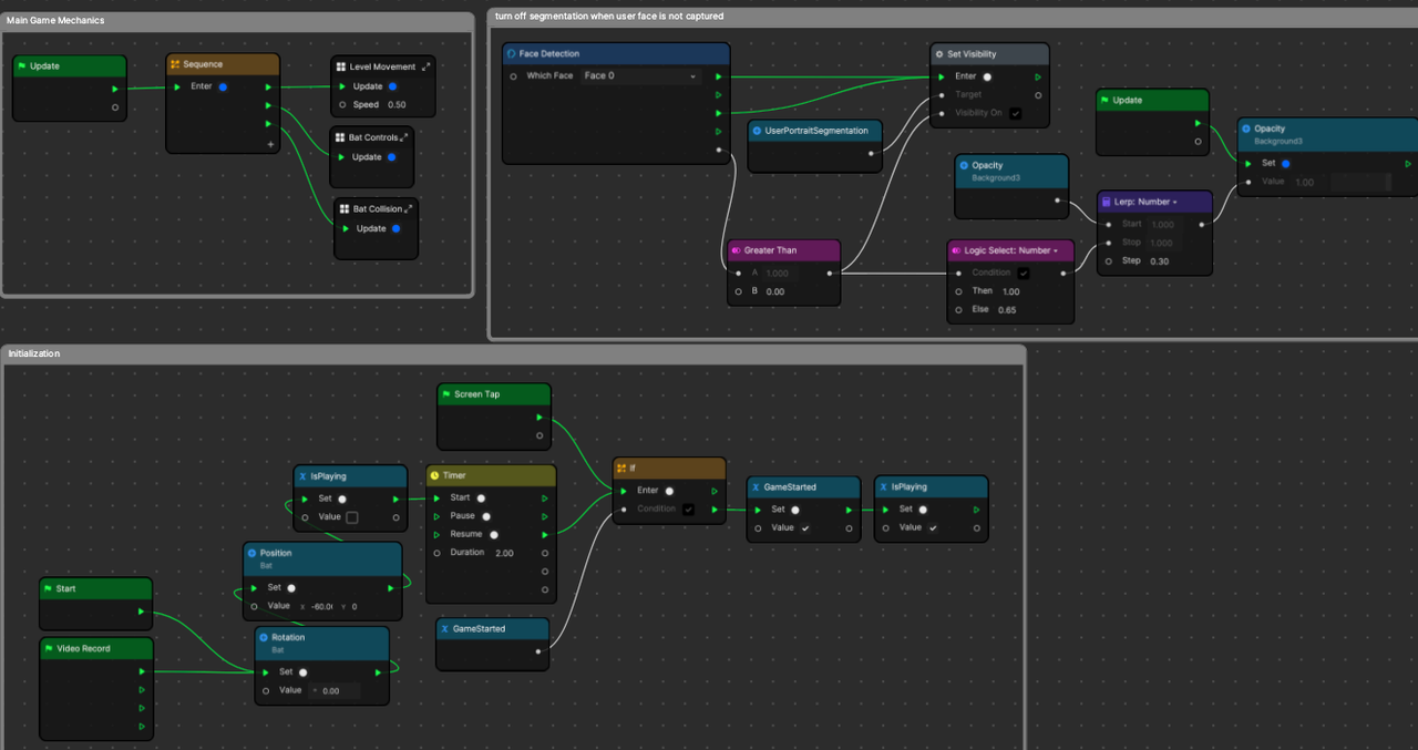
We’ll mostly focus on the main game mechanics since that is the main purpose and scope of this MicroJam project.
It’s important to note that a Sequence node is used to pass an Update signal to all of the game mechanics in a specific order for every single frame.
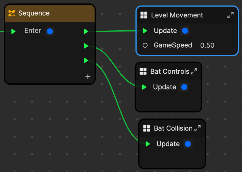
The logic will be much more robust if we pay careful attention to the order that we do things. In this example, we move the level, including background, foreground, and pillar objects. Next, we adjust the bat character with our Bat Controls subgraph. After those two are set up, the third subgraph is able to calculate the collision based on all objects’ final, end-of-frame positions.
Level Movement Subgraph
The Level Movement subgraph has an Update signal input so that we can execute some small amount of code for every single frame. It starts off with a check, “If IsPlaying == true”.
IsPlaying is a variable we created to check if the game has started, but not ended. It’s just telling us if “the player is still alive.” The following sections will only be executed when the player is alive, so essentially the background will stop scrolling when the bat dies, and the game will appear to freeze.
We keep a value called ControlledTime, which keeps track of the time that has passed while IsPlaying has been true. You can see that it adds deltaTime to the variable for each frame that this executes. Changing the GameSpeed input variable will change how much time is added during each frame. For our game, it’s set to 0.5, or half speed.
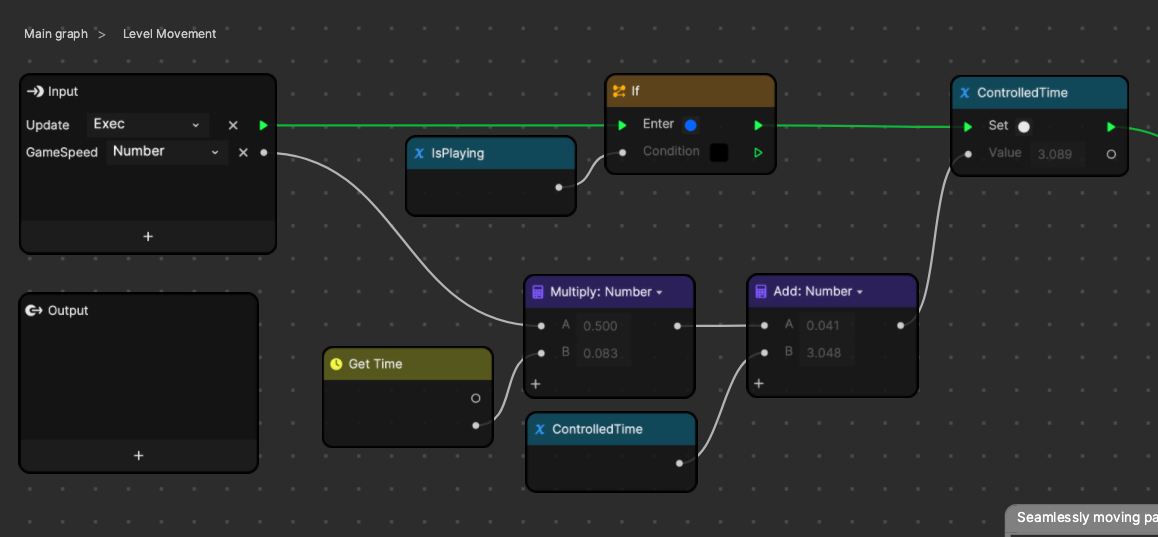
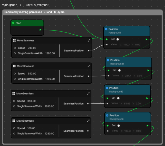
Next, we pass the execution signal onto our Position setter nodes. These will set the position of our background and foreground layers based on some algorithms we came up with inside the MoveSeamless subgraph.
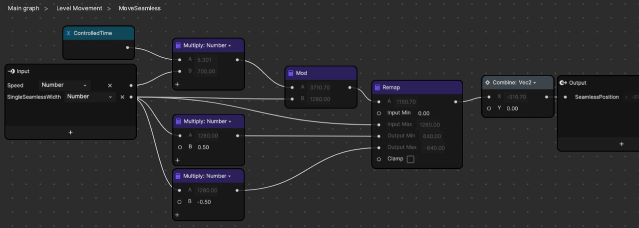
Let’s take a look at the MoveSeamless subgraph.
- Speed is in pixels per second.
- SingleSeamlessWidth is the actual value of one repetition of your seamless background. Your tiled image will be two images wide for this technique. In this example, our layers are squares and full screen on our 720×1280 reference canvas, so the width of the square is 1280. You can find this value by multiplying Size and Scale of the 2D image’s Transform.
- SeamlessPosition (output) is the golden position that our subgraph creates to tell us where to position the layer based on the current ControlledTime.
Looking at MoveSeamless, we can see that Speed is multiplied by the time to get the current position. We can then use Mod to make sure that whatever this value is, it will keep looping in that 0 to B range. In this case, B is going to be SingleSeamlessWidth, which is 1280, the actual canvas pixel width of our square background layer.
If we were to output this as is, the layer would shift from 0 to 1280 over and over, at our specified speed. We must center that range, which is why we use the Remap node. Remap will take our current value, and convert it from our old range (0-1280) to our new range (-640 to 640).
Since the total width of this range is 1280 for each of these ranges, we can just subtract 640. Remap is more flexible and a great node to know how to use.
Lastly, we output the new position to the output of the subgraph. This subgraph is duplicated and used for each layer of foreground and background.
For our pillars, they are not wider than the screen, so we will use a modified version of the same tricks from above. We’re essentially doing the same thing, but let’s dive into it.
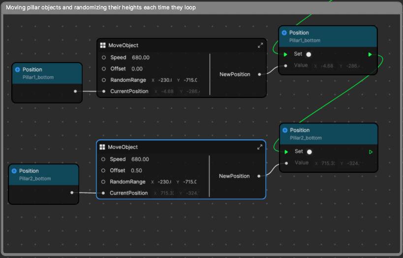
Let’s take a look inside the MoveObject subgraph.
- Speed is in pixels per second for the object to move right to left.
- Offset is a value from 0.0 to 1.0 that offsets it up to one full pass across the screen. Notice how one pillar is set to 0.5 so that it comes during the opposite phase of the first.
- RandomRange is a range from X to Y that affects the height of the pillar objects. The range is set so that -715 places the gap between the pillars at the bottom of the screen, and -230 places it at the ceiling.
- CurrentPosition is the current position to track when the pillar wraps around, and also the current height.
If we take a look at the top row, we’ll see a logic that breaks down to the same thing as the MoveSeamless subgraph.
Remember how we mentioned we could swap out the Remap node and just subtract 640 to create some centered values instead? Well instead of 1280 and 640, this time we’ll use 1440 and 720 to give some extra horizontal space in between pillars.
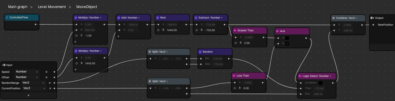
The extra logic we’ve added towards the right half of this subgraph will pass along the current Y value, or vertical position of the pillars. Sometimes the pillar’s previous X position is negative, and then the next X position is positive. This means the pillar snapped from the left side, back to the right side, and is now ready to start moving past the screen again. This happens one time for each cycle, when the pillar resets to the right. Below is a GIF showing a real-life reenactment if the pillar was moved with a mouse instead of Visual Scripting.
It’s ok if you don’t fully absorb the fine details of this. The most helpful way to learn is by changing the values in the subgraphs and seeing how they affect the game. Try changing the Offset, RandomRange, or Speed input values, or maybe even add a third set of pillars!
Bat Controls Subgraph
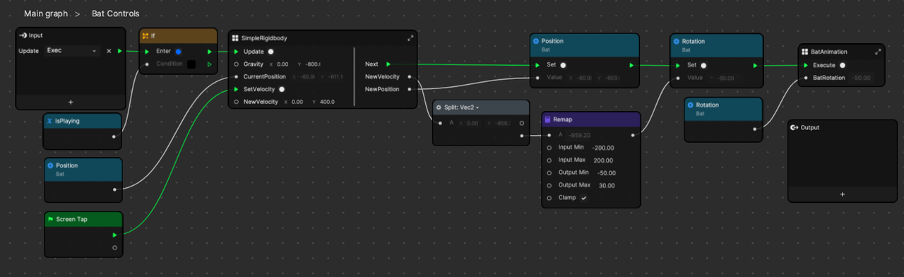
The Bat Controls subgraph has no inputs or outputs, other than the Update signal. We can see that a huge portion of the bat controls are handled by two subgraphs–SimpleRigidbody and BatAnimation.
Just like with the LevelMovement subgraph, we have an If node that blocks execution unless IsPlaying is true. Next we feed the current position into the subgraph and our passive Gravity force will affect the bat’s acceleration, velocity, and position. These can then be output and we can set the bat’s new position.
You may also see that we’re using the bat’s current velocity to set the rotation. This is a design choice, because the bat looks better when the direction of movement (velocity) correlates directly with the direction that it’s turned (rotation). When it is moving up fast, it looks the most upward.
Let’s take a look inside the SimpleRigidbody subgraph. This might be the most reusable subgraph from the whole project, so we spent extra time making it as general and useful as possible.
- Gravity is the constant force acting on the object and it correlates to pixels per second squared, much like how real-world gravity is 9.8 meters per second squared. You can think of it as a constant force that accelerates the bat. If you reuse it, gravity doesn’t even have to be gravity, as you can code in any directional (x,y) force you want.
- CurrentPosition is the current position of the bat that must be passed so that you can calculate the next position of the bat, based on forces and current velocity.
- SetVelocity and NewVelocity are the inputs that go together and basically represent an impulse force. Instead of gradually accelerating an object to a certain speed or direction, you can instantaneously set the bat’s velocity. We use this to make sure the bat hops in a very tight and snappy way which feels satisfying to whoever is playing the game. Having “tight controls” is one of the top positive comments game reviewers leave in modern reviews, so it’s important to think about this part.
The simplest part of this subgraph is the SetVelocity and NewVelocity inputs, which are piped directly into one setter node. We can do this because the event that is passed in is the Screen Tap node event, OnStart. It’s as simple as saying, “when the user taps, hard set the velocity of the bat.” The gravity will quickly accelerate the bat downwards again within a few frames.
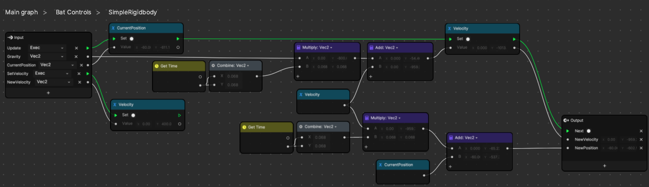
The GetTime node not only gives us the time–the time that has passed since the effect first loaded–but it also provides the DeltaTime, which is the time between the current and last frames. You’ll notice we use it when calculating velocity and position. The best way to explain it is that our velocity is in pixels per second.
If our current velocity is 0 and we have gravity of 800, then it means that after one second, our velocity will become 800 pixels per second (0 + 800 = 800). After another second passes, it will become 1600 pixels per second, and so on. So then how do we calculate how much this acceleration value (gravity) will change the velocity value after less than one second? We can multiply the amount of time by the acceleration.
Assume the starting velocity is once again 0 and gravity is 800. After 0.070 seconds, the velocity should become 56 pixels per second. See the following calculation:
0 + (0.070 seconds * 800 pixels per second squared) = 56
This is all just math, so we won’t spend any more time picking it apart. After NextVelocity and NextPosition are calculated, we just pass them out of the subgraph so that they can be applied to our bat.
The Gravity and NewVelocity inputs are both Vector2 values where we left the X values as 0. This lets us affect the bat’s motion in only the Y direction for our purpose without moving horizontally at all. It should be noted that the subgraph can actually be used without modification in other projects to move objects or characters in a full 2D range across X and Y positions.
After our bat is rotated and vertically moved, we need to animate it with varying textures to make it look like it’s really flying. This is another part of the “tight controls” mentioned before. We pass in the BatRotation because we want the bat to animate differently depending on how it’s rotated. This makes the bat look more interactive and crisp instead of always playing the same flapping animation regardless of where it’s turned.
When a creature is flying, it’s naturally working a little harder if it’s moving up, and can relax more when it’s falling downward. To reflect that, we have some textures that represent big flaps, medium flaps, and no flapping (dive). You can use animation sequences to create the animation, but because our assets are of only two textures each, we will use an alternate method that may be valuable to know.
First, we pipe the rotation value into a remap that translates our rotation range from -50 through 30 to 0 through 2. Now we know our output of this remap node will always be either 0, 1, or 2 depending on the rotation. We can think of those values like the state of the bat.
- 0 is when the bat is pointed down, falling fast.
- 1 is somewhere in between 0 and 2, so somewhere in the medium space. The bat will flap normally, as if maintaining altitude.
- 2 is when the bat is pointed upward, flying up as hard as it can with big flaps.
This representation is realized when we plug them into a Switch node, where it will take in the values and then choose which of the signals to send–0, 1, or 2. Those signals will end up setting the correct texture for the bat’s current rotation.
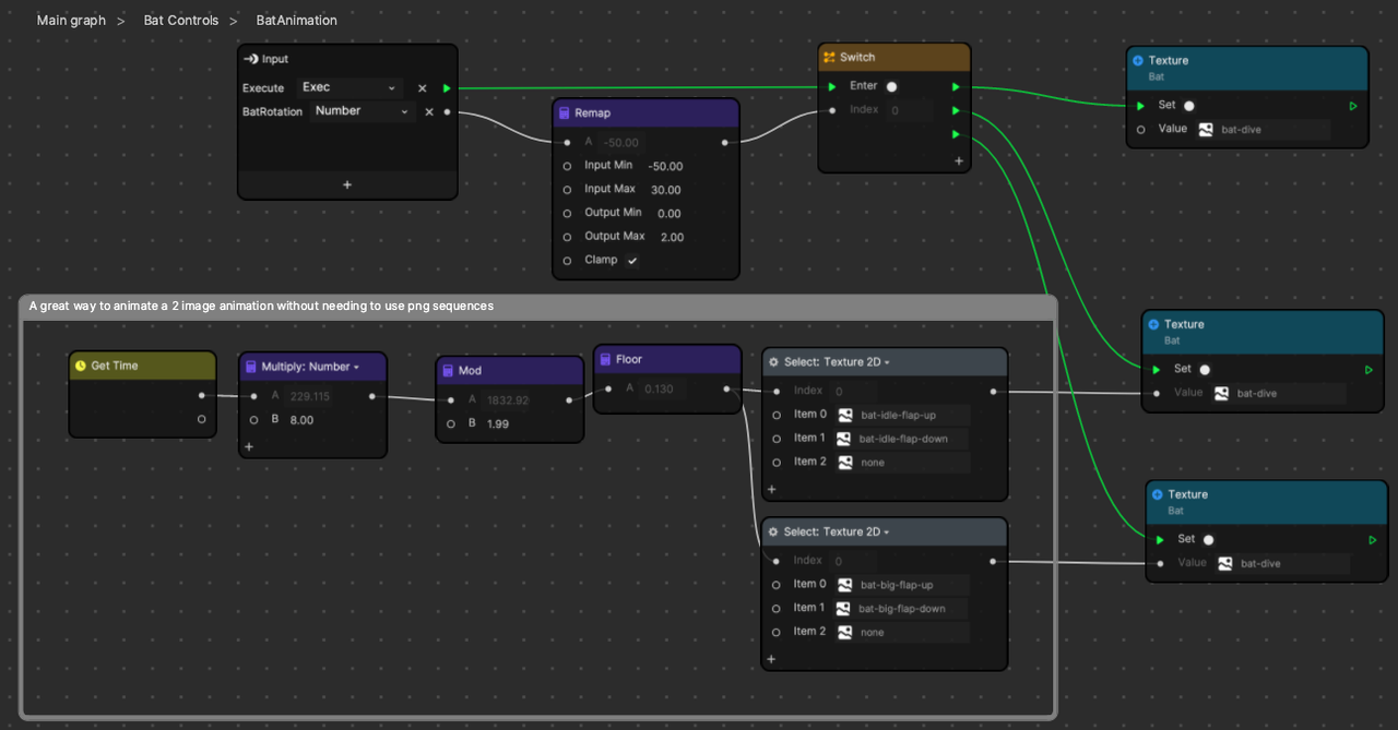
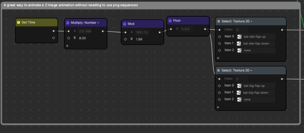
Just to zoom in on the two texture animations, we’re using GetTime, multiplying it by 8 to speed it up, and then taking a Mod value to continually make it loop from 0 to 1.99.
Then we use a Floor node to tell it to round down to either 0 or 1, whichever value is closer. This is a simple setup to create a value that keeps flickering between 0 and 1, eight times every second, or four full flaps per second.
The Select node takes in the 0 or 1 value and uses that to determine whether to output the item 0 texture or item 1 texture.
Again, we’re at the end of another major section. You are encouraged to play with the values and see how they change the feel of the game.
Adjust the gravity or jump velocity. Even change the values in the remap nodes to adjust how much the bat rotates in response to its velocity. Playing with the project in an exploratory way is one of the key ways to learn how things work. If you’re able, try making it so that gravity and jumping direction flip every time the user taps. It feels pretty wild!
Collision Detection Subgraph
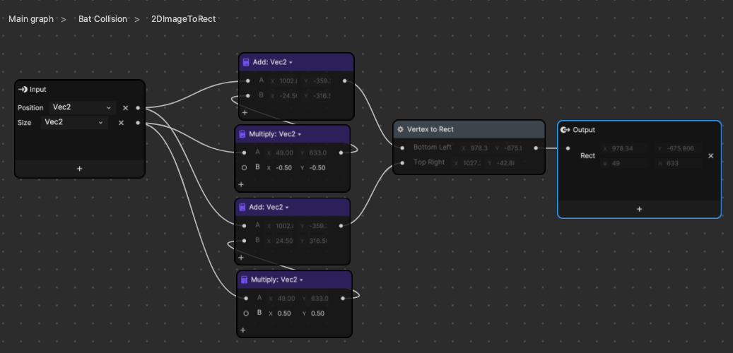
The Bat Collision, or collision detection, subgraph has a few more golden nugget subgraphs that are very portable and reusable. Here we use 2DImageToRect to calculate a rect, which is a necessary input for the PointInRect node. PointInRect will take in a rect, which is a relatively standardized data type used in a lot of graphics situations. It represents a rectangular orthogonal area, that is, a rectangular area that is always aligned with the x and y axes. These rects cannot be rotated.
Once we define a rect, we can pass it into PointInRect and that node can tell us if the DetectPoint (the other input) is a point that is within the boundaries of the rect. We’re going to use this node to determine whether the bat is within the rect. The rect represents the pillars that are passing by the bat. If the bat ever ends up overlapping with those pillars, we say that the bat is smashing into the pillar, and it’s game over. This is why the resulting output of PointInRect will set IsPlaying to false.
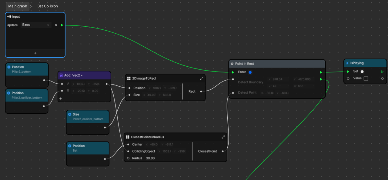
2DImageToRect doesn’t do a ton of heavy lifting but it contains a logical chunk of Visual Scripting into a self-contained area. It also allows us to copy and paste that chunk around more easily for a readable and quick repetition of logic. Notice that this chunk of logic shown above is repeated for each pillar.
When we zoom in and focus on the inputs of this subgraph, we can see we’re adding the position of the pillar collider to its parent SceneObject. This is the only way to get the final screen pixel position of the object, adding up the positions of itself to its parents.
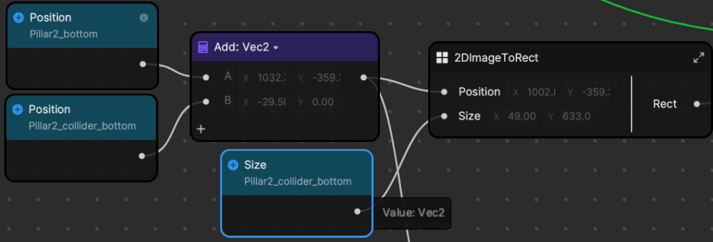
Inside we can see that we’re just taking in the position and size of the rectangular image and calculating what would be the bottom-left corner of that rectangle, and the top right. These two values are enough to define a rect and output it.
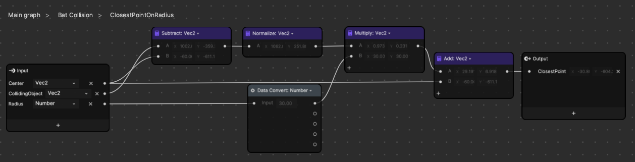
The ClosestPointOnRadius subgraph will take in the central object (bat) and a target object (a pillar), and calculate the nearest point on a certain radius from the bat to the pillar. For simpler logic, you should just use the rectOverlap node. The main reason we cannot easily use the RectOverlap node is because our bat rotates a lot, and as mentioned before, we can only define rects as orthogonal (axis aligned and not rotated).
This subgraph is surely a more obscure and specialized way to detect collisions. Essentially what it’s doing is creating a vector that points from the bat to the pillar, and then outputting a point that is “radius” pixels away from the bat in that direction. If we define the bat’s boundaries as a circle, and because a circle has infinite points around its radius defining its boundaries, you can’t possibly check them all. We’re simply finding a point that is on that radius pointing directly towards the pillar. This will most likely be the point to collide with the pillar first. The reason this seems more complex is because we’re combining a circle collider with a box collider. Circle to circle, or rect to rect, are both much simpler to explain and calculate.
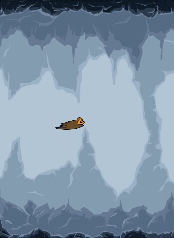
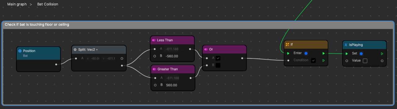
At the bottom of the BatCollision subgraph, after all four pillars are checked, we can pass along the signal to one final check. This is pretty straightforward, but we check if the bat’s position is below the cave floor, or above the cave ceiling. When the bat touches the floor or ceiling, it’s game over all the same.
To wrap this section up, we want to once again remind you that it’s ok to feel like some parts are difficult to grasp. We encourage you to open the project up yourself and play with it. If the collision is what’s stumping you, then try some visualizations. Create a small 2D image and set its position to the output of one of the ClosestPointOnRadius subgraphs to see visually where that point would be! Also, if you set the visibility of the pillar colliders to “true,” you can visually see where those collider rectangles will collide with the bat.
More Project Ideas
Now that we’ve completed this project, try to complete the following exercises:
- Easy: Make the level move faster as the player survives longer.
- Medium: Create a game ending scene and fade it in when the bat dies.
- Challenging: Make the bat follow the user’s nose, or head rotation.
- Extreme: Give the bat three hearts, or lives, and let it collide with three pillars before it dies.
If you create anything with any of our MicroJam projects, please share it in the Effect House Discord channel and let us know what parts you used! We love receiving your feedback and seeing the amazing things you create.
Thanks for following along! Stay tuned for more MicroJam projects.