Visual Scripting Module 5: Understanding Execution Order
Control flow is the driver of a visual scripting graph, since the sequence of commands passed between nodes dictates when and how things should happen. Visual scripting graphs typically leverage initiator nodes like event nodes or detection nodes to tell the script to run. Downstream logic is subsequently triggered.
Execution Order for Visual Scripting Logic
Execution describes how the computer reads and fulfills the instructions in a visual scripting graph. Execution order more specifically refers to the sequence in which commands are carried out in a control flow. Essentially, execution order is the step-by-step recipe that tells your computer to carry out commands in a specific order. Execution order is important for several reasons:
- Dependency: Proper execution order ensures tasks relying on prior outcomes work correctly.
- Sequential logic: Many logic flows are designed to be sequential. Changing the order might produce a wrong output or cause the algorithm to fail.
- Event-driven operations: The order in which events are handled and processed can determine the flow and behavior of the effect.
- Performance: The order of operations may impact performance. Executing certain tasks earlier might enhance caching, prefetching, or other optimizations.
Initiator nodes may also have different execution frequencies, which affects how the visual scripting graph is run for every frame of the video. For example, the Start node executes only once when the effect is started, while the Update node executes continuously for every frame of the video.
Node Execution Demo: Numbers
Now let's take a look at an example of a visual scripting graph that displays numbers using the Text object. Examine the graph below and note how the data flows and when commands are executed.
The graph basically illustrates the following JavaScript snippet:
SetText(DataConvertToString(GetNumber(NumberVariable)))
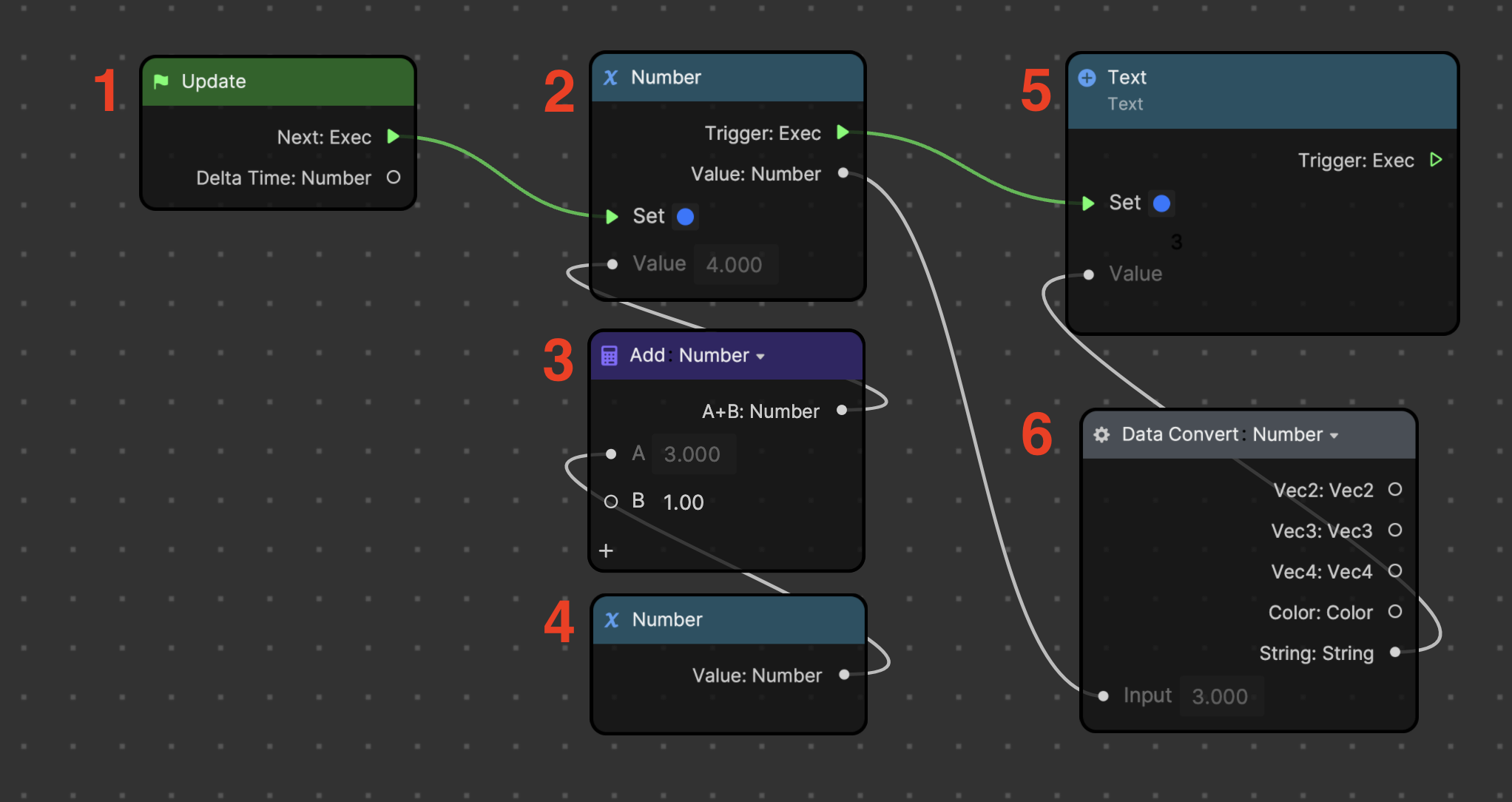
This graph adds a value of one to a number, converts the sum into a string data type, and then outputs the value so it can display on the Text object. The graph uses the following logic:
- Update: Used as the initiator node to start the flow of logic. It executes downstream logic for every frame of the video.
- Number (Set variable): Takes the command from the Update node to Set the value of the Number variable, which means that the number will increase by one for every frame of the video. This Number variable was added using Set variable, which means that the node assigns or changes the value of the variable, instead of simply retrieving it. In this case, this Number node sets the sum of the two nodes beneath it (nodes 3 and 4).
- Add: Simply adds the values of its inputs, and outputs the sum. The B input of the Add node has been set to one. Therefore, the Add node adds a value of one to the retrieved number beneath it.
- Number (Get variable): Added to the Visual Scripting panel using Get variable, which simply retrieves the value of the number.
- Text: The Text node is added to the Visual Scripting panel using Set Text from the Text property of the Text component. The Number variable (node 2) commands the Text node to set its value to the sum of the added numbers. However, the number must be first converted to a string to display in the preview.
- Data Convert: Converts the data type of its input value. In this example, the value of the sum is converted from a number to a string, so it can be recognized as a sequence of characters instead of a numerical value. This node is especially useful for moderating compatibility between nodes, since some nodes only accept inputs of a certain data type.
Use Event Nodes to Execute Logic
Consider how nodes from the Event category can be used to start the control flow of the number graph. Event nodes execute downstream logic in response to a particular event.
Try connecting the Exec outputs from each node from the Event category to see how the effect responds to different execution functions.
Use Detection Nodes to Execute Logic
Nodes that detect appearances or behaviors can also be used to execute downstream logic. Apply your knowledge of detection nodes and control flow to initiate the previous number graph example. Observe what happens when you try different control flows from different detection nodes.
If the node has a customizable parameter (for example, Facial Movement or Gesture), be sure to change it to your desired setting. Preview media may not be available by default for every behavior, so you can upload your own media or use the Camera function in the Preview panel to test out the effect.
Key Terms
- Execution order
- Get variable
- Set variable
Next Steps
In the next module, you will learn how to apply basic math concepts to visual scripting.