Create a Depth of Field Effect Using Spritesheets
Use spritesheets to create a depth of field illusion, making objects appear further away, closer, larger, or smaller than they actually are. In this tutorial, we will apply this and other techniques to create a confetti effect in the Visual Effects (VFX) Editor.

Set up your VFX environment
After you've created a new project in Effect House, you will need to set up a VFX environment. You can utilize one of the two methods outlined below. For more information on the VFX Editor, check out the VFX Editor Overview.
Method 1
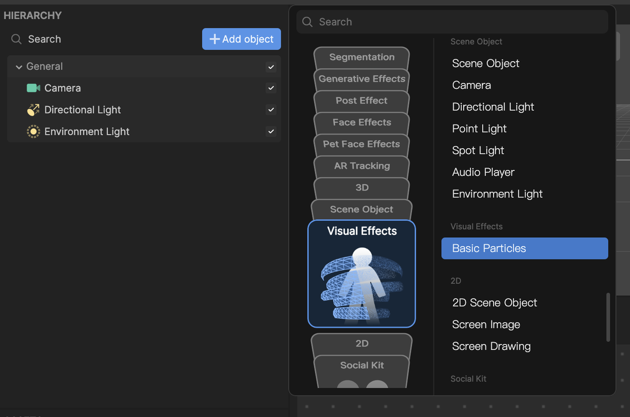
- Go to the Hierarchy panel
- Click the Add object button [+]
- Go to Visual Effects
- Select Basic Particles
Method 2
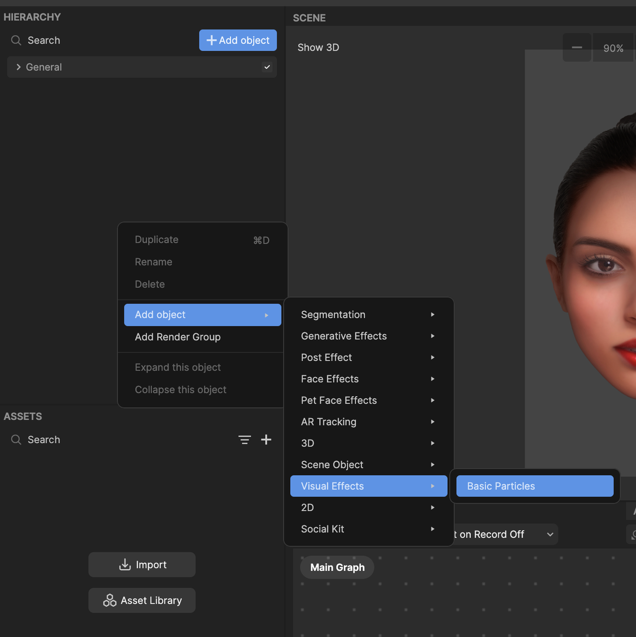
- Go to the Hierarchy panel
- Right click on the panel to view the menu popup window
- Navigate to Add object
- Go to Visual Effects
- Select Basic Particles
Once you've added the Basic Particles object, you will see the Visual Effect Graph. You should also notice white particles moving in the Preview panel.
To see your changes immediately as you make them, enable the Auto Compile option by clicking the Auto Compile button. If this option is not enabled, you’ll need to manually click the Compile button after each update to view your changes.
Import a 2D texture
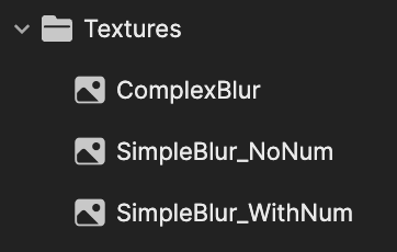
You need a 2D spritesheet texture asset with multiple blur levels. To get started with this tutorial, you can import the following file:
To import a 2D Texture asset:
- Go to the Assets panel
- Click the Add asset button [+]
- Go to Import and click From Computer
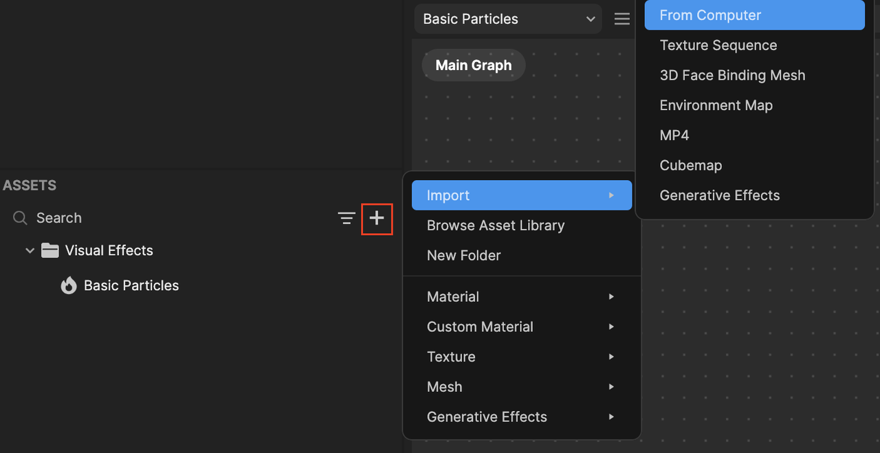
- Select and import all 3 images that were included in the zip file
Learn basic depth of field
So, how do we set up the VFX editor so that the particles look blurry when they are closer to the camera?
You can achieve this by assigning a specific texture index from the spritesheet based on particle's Z position. Let's look into how this is set up.

Initial set up
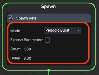
In the Spawn logic, change the Mode to a Periodic Burst, so that we can spawn a number of particles periodically using a delay:
- Go to Mode and choose Periodic Burst
- Set Count: 300 particles
- Set Delay: 3 seconds
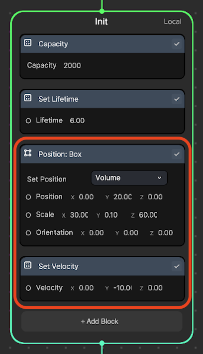
In the Init logic:
- Delete the Set Random Velocity node
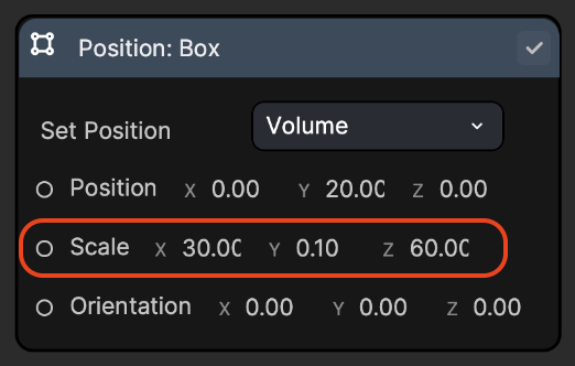
- Add a Position: Box node and set the Position: (0, 20, 0) and Scale: (30, 0.1, 60).
- This maintains the particle's spawn location within a box shaped area.
- Setting the position to (0, 20, 0) allows the particles to be spawned from the top of the screen.
- Setting the scale to (30, 0.1, 60) creates an invisible, horizontally aligned rectangular box where particles will be spawned within.
- Add a Set Velocity node and set Velocity: (0.00, -10.00, 0.00). This creates a falling down motion.
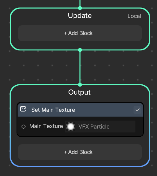
For now, keep the Update and Output logics to their default settings.
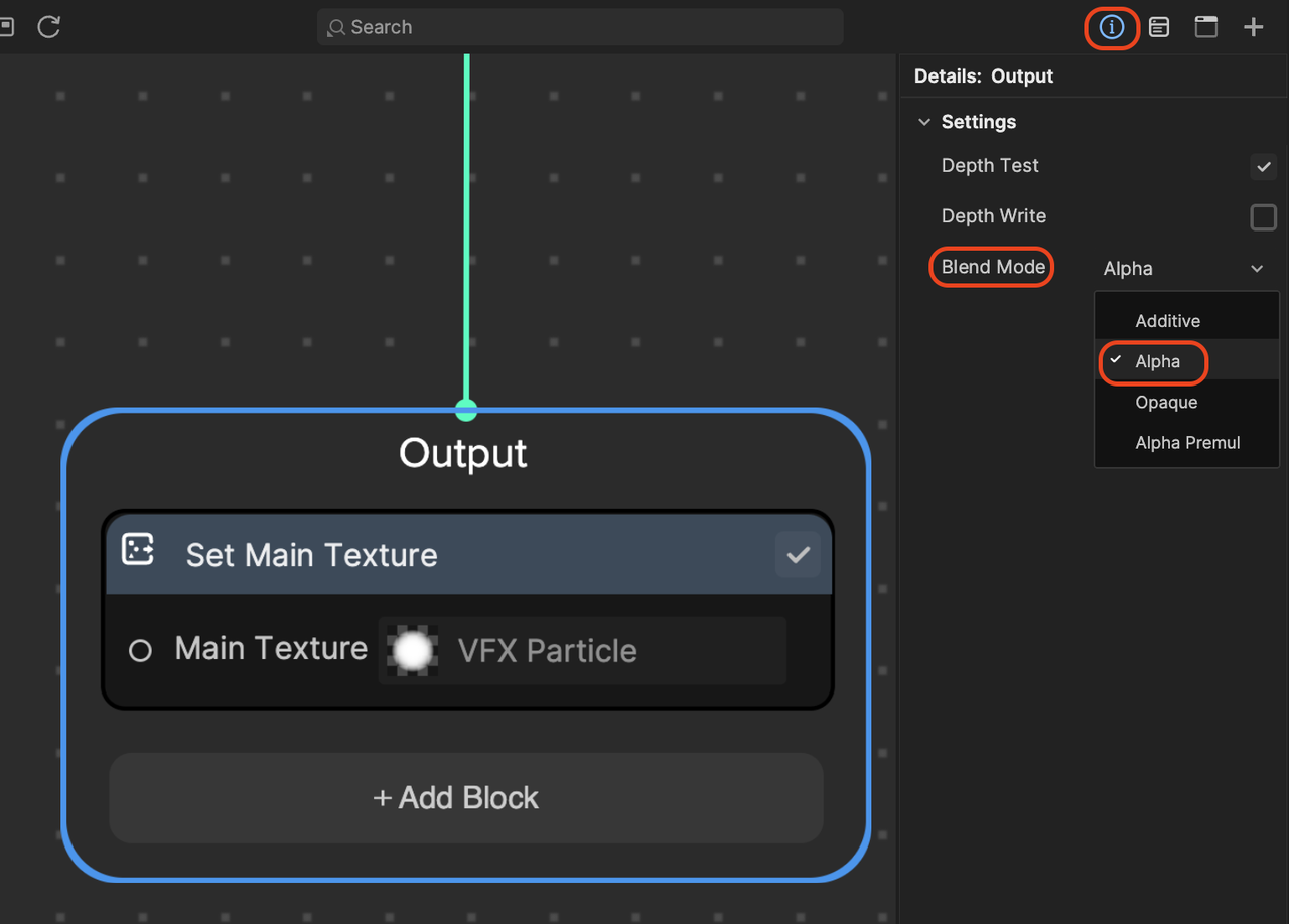
We also need to change the Blend Mode from Additive to Alpha to see the actual color of particle without blending with the background color.
To change the Blend Mode:
- Go to the Visual Effects panel
- Click the Details button [i]
- Click the Output context node (a setting window will pop up in the details panel on the right)
- Go to Blend Mode and choose Alpha
The particles should spawn in a long, shallow box shape from the top of the screen and move downward. For now, the particles appear white.

Set texture index based on particle Z's position
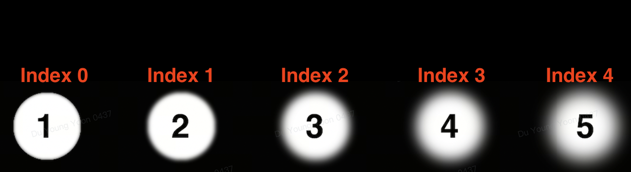
So, how do we assign a specific texture index from the spritesheet below based on particle Z's position?
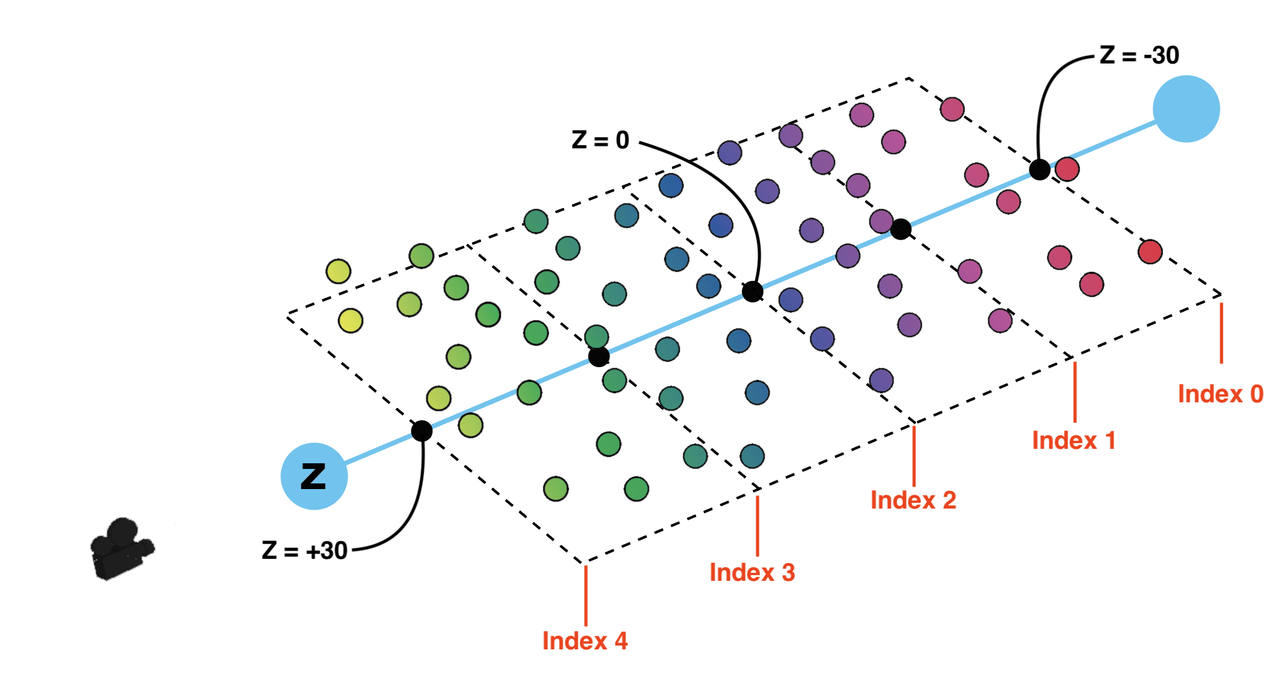
Let's revisit the particles' positions when they are spawned. Below is a diagram showing how particles are positioned within the spawn box in the scene.
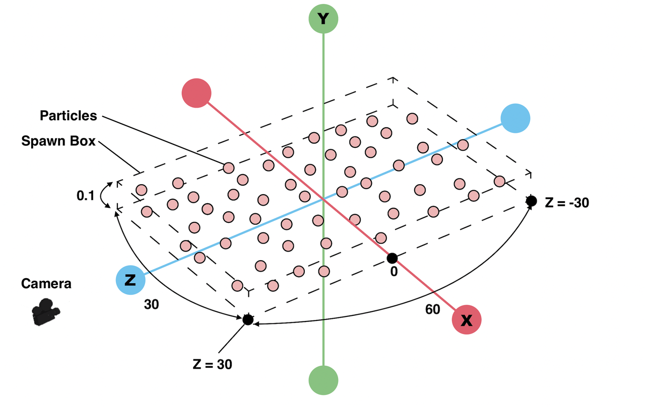
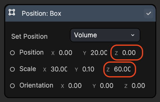
There is a spawn box with a size of (30, 0.1, 60) where particles are spawned.
Since the spawn box's Z position is 0, the box boundary will go from -30 to 30 along the z axis.
Based on what we learned from above, we need to adjust the distance range (-30 to 30) to the texture index range (0 to 4). The goal is to choose higher values to make it blurrier as a particle comes closer to the camera.
To convert the range (-30 to 30) into (0 to 4), let's use the Remap node.
In the Update logic:
- Add the Get Position, Split, and Remap operator nodes
- Connect Get Position to Split, Split to Remap, and Remap to the Set Texture Index node
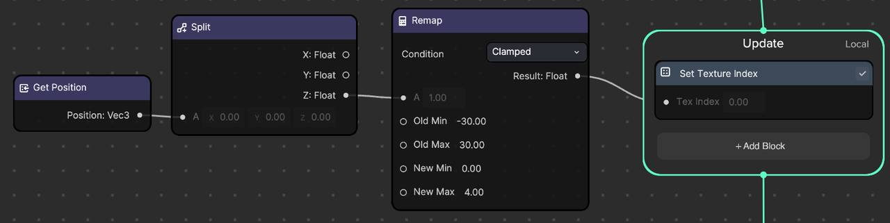
- Get the particle's position data using the Get Position node
- Use the Split node to split the x, y, z positions
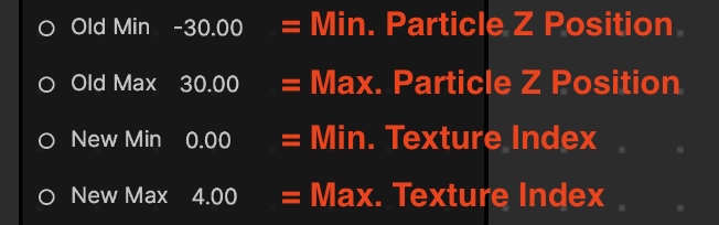
- Convert the old min and max ranges (-30 to 30) to the new min and max ranges (0 to 4) using the Remap node
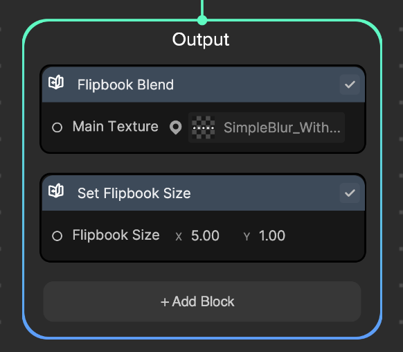
In the Output logic:
- Delete the Set Texture Index node and add the Flipbook Blend node
- Go to the Flipbook Blend node
- Click SimpleBlur_WithNum
- Add the Set Flipbook Size node and set x: 5, y: 1, since we have 1 row and 5 columns in the SimpleBlur_WithNum image
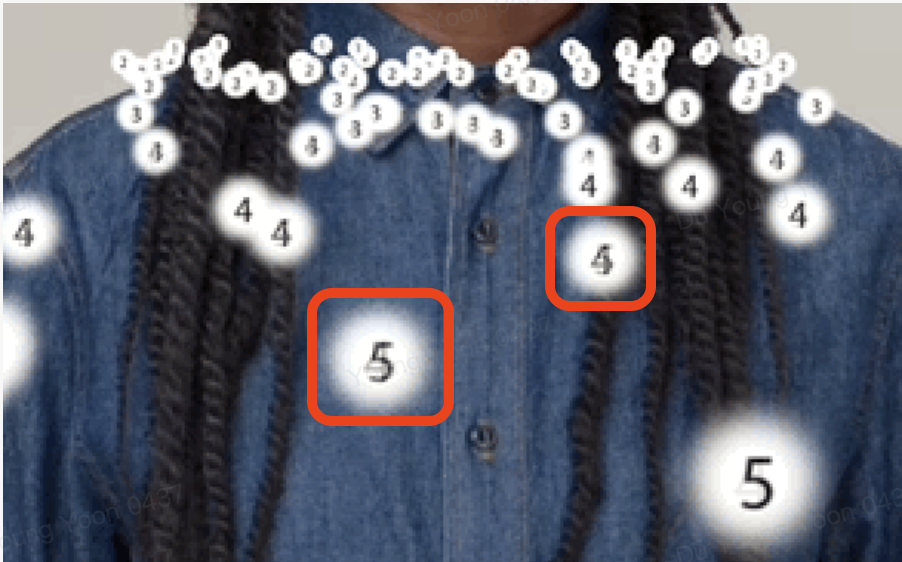
You can see the number 5 particles are closest to the camera followed by 4, 3, 2, and 1.
Notice that two images will be blended together if the texture index is not a whole number. For example, images of 4 and 5 are mixed as the texture index was set to a float number between 4 to 5.

The depth of field looks more obvious if you change the main texture to SimpleBlur_NoNum.

Advanced depth of field
Now that we have learned the basics, let's dive into a more complex case. We'll build out a confetti effect with multiple variations in shapes and blur levels.

The spritesheet for this example has 3 variations in shape (y:3) and 5 variations in blur level (x:5).
Add further logic
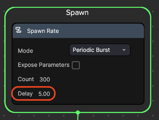
In the Spawn logic, increase the Delay to 5 seconds.
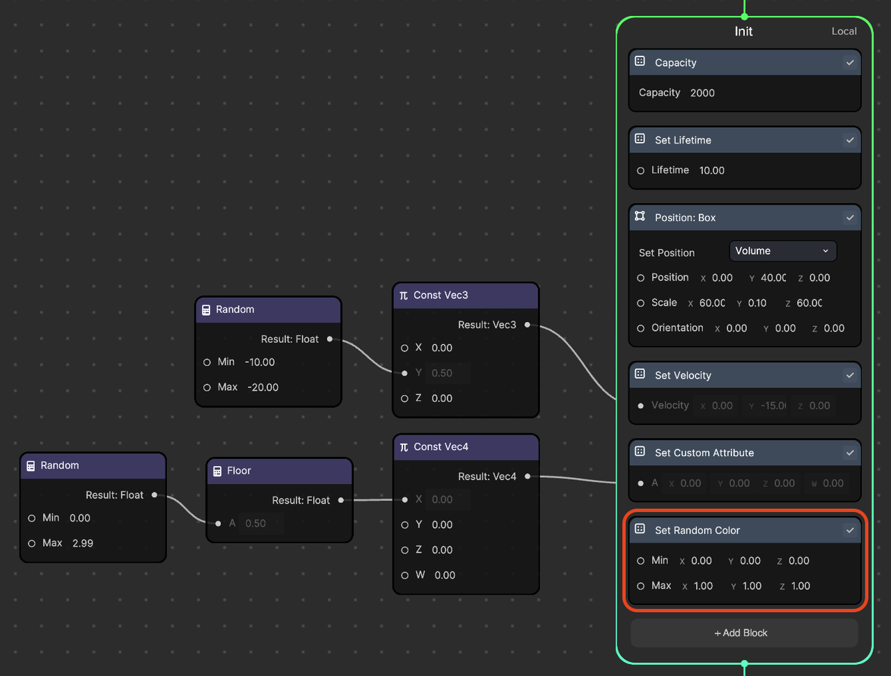
In the Init logic:
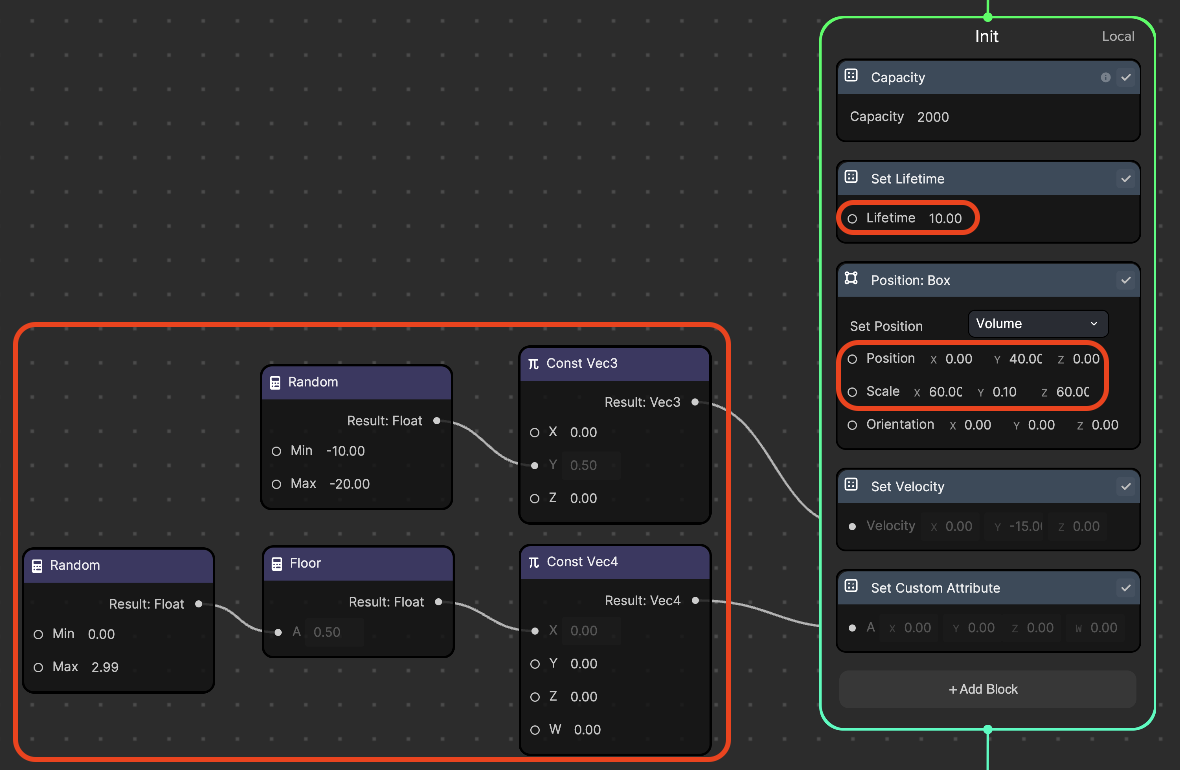
In the Set Lifetime node, set Lifetime: 10. This will allow particles to appear for 10 seconds.
Add the Random and Const Vec3 nodes.
- Connect Random to Const Vec3 and Const Vec3 to Set Velocity, as shown in the screenshot above.
- In the Random node, set Min: -20, Max: -10. This will give a downward velocity to each particle from a range between -10 to -20.
In the Position: Box node, set position: (0, 40, 0) and set scale: (60, 0.1, 60). This will locate the spawn box above the camera viewport with a wider area. As the particles fall, they will move into the camera view.
Add the Random, Floor, Const Vec4, and Set Custom Attribute nodes.
- Connect Get Position to Split, Split to Remap, Remap to Floor, and Floor to the Set Texture Index node, as shown in the screenshot above.
- In the Random node, set Min: 0, *Max: 2.99
- In the spritesheet, there are 3 shape variations. We want to store one of 3 integers [0, 1, 2] for each particle.
- Remember, the Floor node rounds the input value down to the nearest integer. Therefore, the Max value should be less than 3, which is 2.99.
- The Custom Attribute node has a Vec4. Since we just need to store a float number, we can store it as an x value. By using Set Custom Attribute or Set Target Position in the Init logic, we can store an initial value, a whole number in this case, for each particle. This will be used later in the Update logic to pick the correct shape.


In the Update logic:
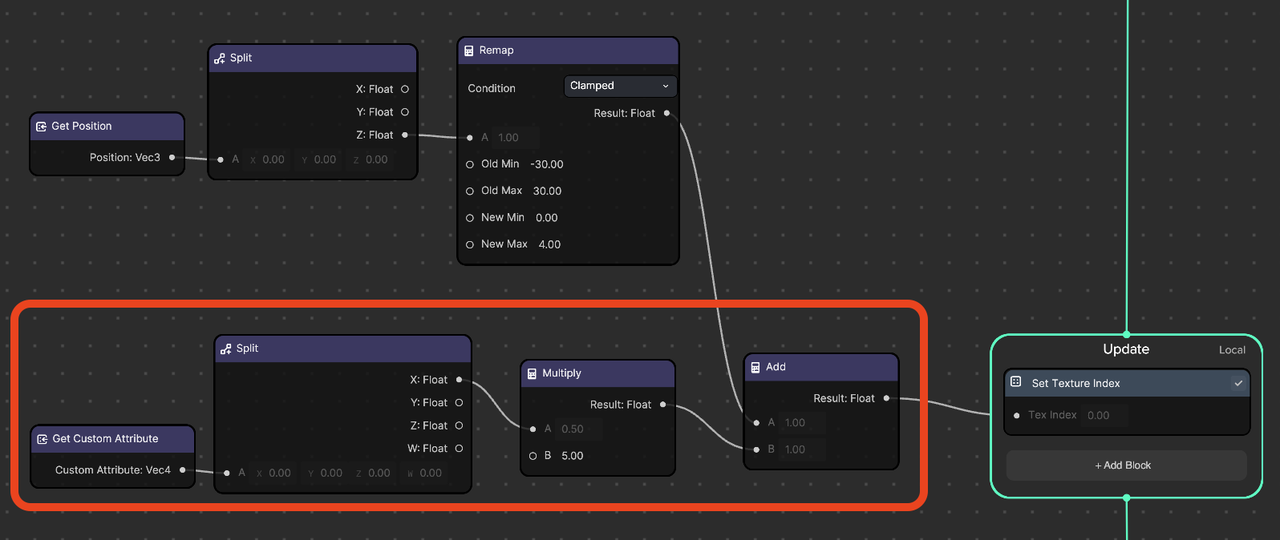
- Add the Get Custom Attribute, Split, Multiply, and Add nodes.
- Connect Get Custom Attribute to Split, Split to Multiply, Multiply to Add, Remap (existing) to Add, and Add to Set Texture Index, as shown in the screenshot above.
- We are using the Get Custom Attribute and Split nodes to get Custom Attribute's x value from the Init logic, which has a float value of 0, 1, or 2 .
- In the Multiply node, set B: 5. We are multiplying by 5 because each shape has a total of 5 blur levels.
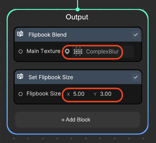
In the Output logic:
- In the Flipbook Blend node, select ComplexBlur
- Add the Set Flipbook Size node and set x: 5, y: 3, since we have 3 rows and 5 columns in the ComplexBlur image
We can see 3 different shapes with correctly selected blur levels based on the particle's z position.

Final touches
To refine the effect, let's add some color, rotation, and horizontal speed.
In the Init logic, add the Set Random Color node with the default values (Min: 0, 0, 0 and Max: 1, 1, 1). This will essentially assign each particle a full range of random colors.
In the Update logic:
- Let's add some horizontal velocity as turbulence. Add the Get Velocity, Random, Const Vec3, and *Add8 nodes.
- Connect Random to Const Vec3, Const Vec3 to Add, Get Velocity to Add, and Add to Set Velocity, as shown in the screenshot above.
- In the Random node, set Min: -0.5, Max: 0.5. This will give a range of mild horizontal force to each particle.
- Let's add some rotation to each particle. Add the Get Angle, 2 Random, Const Vec3, and Add nodes.
- Connect the Random nodes to Const Vec3, Const Vec3 to Add, Get Angle to Add, and Add to Set Angle node as shown in the screenshot above.
- In the Random nodes, set both Min: 0, Max: 0.5. This will give a small increment of rotation to each particle.
- Connecting 2 Random nodes to the y and z values will cause rotations in the y and z axes.
Working with blur levels really refines the effect!
xs